Wall
![]()
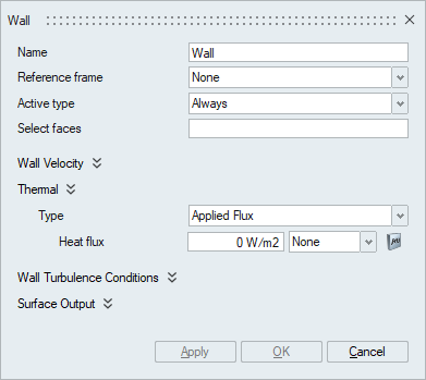
This panel is used to define a no-slip wall, thermal and Turbulence Wall boundary conditions in a flow problem. It can be applied on faces/face groups of volume meshed bodies.
Description
- Active typeThe active type option becomes available only when the Moving Mesh is enabled in the Solutions panel. This option is used to specify when the wall boundary condition is active.
- The default is Always and should be selected when the wall boundary condition needs to be active throughout the simulation.
- None should be selected if the wall boundary condition needs to be disabled.
- The No Interface option should be selected when only surfaces that are not an interface surface or do not find a contact surface of an appropriate medium needs to be specified as wall. This is used for moving mesh simulations.
- Select faces
The select faces option is used to select the faces/face groups that needs to be defined as wall.
- Specify Contact Angle
This option specifies a contact angle model for free surfaces with surface tension. The contact angle is defined as the angle between the outward normal to the free surface and the outward normal to the side boundary. It may be any angle between zero and 180 degrees; it is small for a hydrophilic surface and large for a hydrophobic surface. The contact angle is a function of both fluids and the wall material.
Note: This option will be enabled only when the Immiscible Multiphase flow type is chosen in the Solutions panel.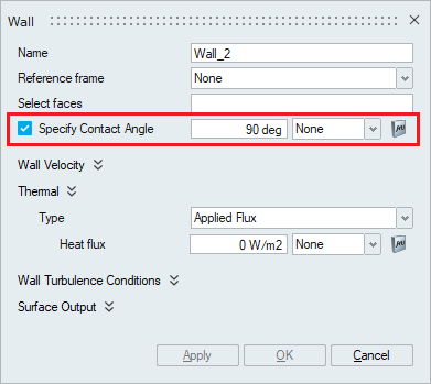
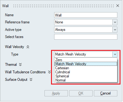
- Wall Velocity
The velocity boundary condition for a wall type may be specified in six different ways, as determined by Wall Velocity Type. A value of Match Mesh Velocity is the default and requires no further data.
The cartesian, cylindrical, spherical and normal wall velocity types allow the wall velocity to be specified in different local coordinate systems.
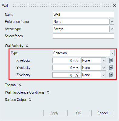
- A wall velocity type of Cartesian uses X,
Y and Z velocities to impose boundary conditions in the global
coordinate system. The Multiplier option can be used to specify
time varying values.
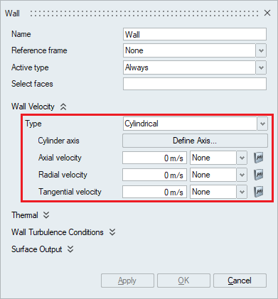
- A wall velocity type of Cylindrical sets
boundary conditions on the axial, radial, and tangential
components of the velocity in a cylindrical coordinate system.
The Define Axis can be used to specify the axis of the
cylinder.
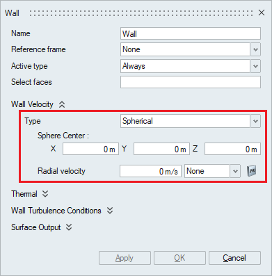
- A wall velocity type of Spherical imposes
a given boundary condition on the radial component of the
velocity in a spherical coordinate system and zero boundary
conditions on the other two components. The Sphere center needs
to be specified in this case.
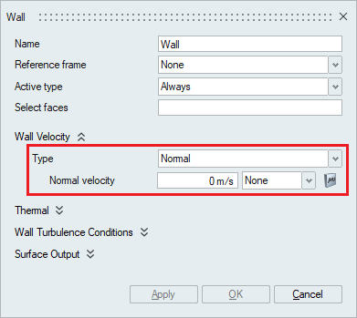
- A wall velocity type of Normal imposes a
given boundary condition on the component of the velocity normal
to the surface and zero boundary conditions on the other two
components.
- A wall velocity type of Cartesian uses X,
Y and Z velocities to impose boundary conditions in the global
coordinate system. The Multiplier option can be used to specify
time varying values.
- Thermal
The Thermal option becomes available in the Wall panel when the Heat Transfer option is enabled in the Solutions panel.
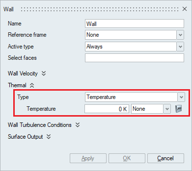
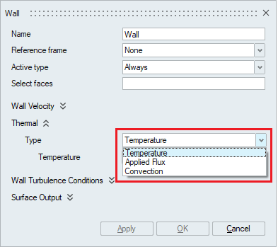 The Thermal wall boundary condition can be specified in terms of Temperature, Applied Flux and Convection.
- Temperature: To specify temperature on
the wall faces, the type should be selected as Temperature and
the value should be specified in the Temperature option. The
Multiplier option can be used to specify time varying
values.
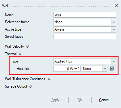
- Applied Flux: To specify Flux on the wall
faces, the type should be selected as Applied Flux and the value
should be specified in the Heat flux option. The Multiplier
option can be used to input scaled values or specify time
varying values.
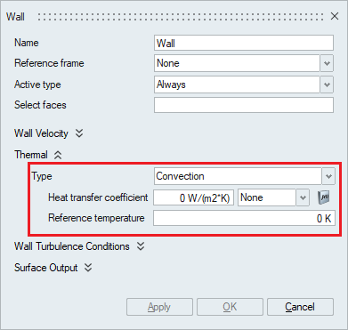
- Convection: To specify convection on the
wall faces, the type should be selected as Convection and the
Heat transfer coefficient and Reference Temperature values
should be specified. The Multiplier option can be used to input
scaled values or specify time varying values.
- Temperature: To specify temperature on
the wall faces, the type should be selected as Temperature and
the value should be specified in the Temperature option. The
Multiplier option can be used to specify time varying
values.
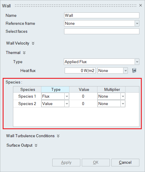
- Species
When the number of species is specified in the Solutions panel, the Species option becomes available in the wall boundary condition panel. The species value should be mentioned appropriately.
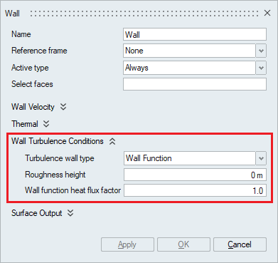
- Wall Turbulence Conditions
This option is used to specify a turbulent boundary layer for the wall.
The turbulence wall type should be specified to define the turbulent boundary layer. Either of the four available options None, Low Reynolds Number, Wall function and Running average wall function should be selected under the turbulence wall type.
- None
The None option should be selected when no wall modeling is required. When this option is set, the surface does not participate in the wall distance calculation for turbulence and no wall modeling is performed.
- Low Reynolds Number
The Low Reynolds number model is used when the Reynolds number of the flow is low and the grid near the wall is fine enough to resolve the flow. It utilizes special damping functions to solve the turbulence momentum equations near the wall. The damping functions substantially reduce the grid number requirement as compared to those needed in their absence.
- Wall Function
High Reynolds number flows on the contrary requires a large number of grid points to accurately resolve the flow at the wall which becomes computationally expensive. The Wall function turbulence wall type significantly reduces the computational requirements by introducing a function to bridge the near wall region. In which case, very refined grid is not required for wall function.
- Running Average Wall Function
The Running Average wall function is similar to wall function but it utilizes the running average variables.
- Roughness height
Roughness height is the average wall roughness height and is used with Low Reynolds number, Wall function and Running average wall function turbulence wall types.
- Wall function heat flux factor
It is a constant factor used to scale the turbulent thermal conductivity within the first element off the wall. This is used with Wall function and Running average wall function turbulence wall type.
- None
- Surface Output
Surface Output specifies the output parameters for a boundary face.
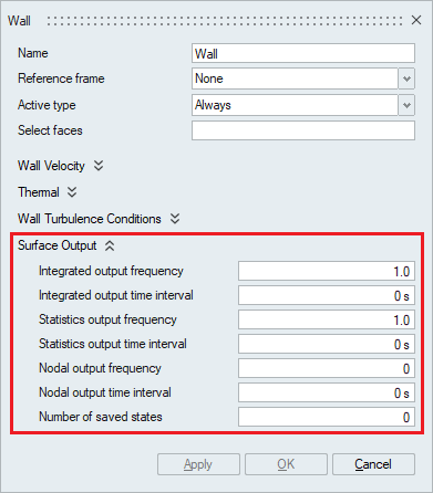
- Integrated output frequency
Time step frequency at which the integrated surface quantities are output. If zero, this option is ignored.
- Integrated output time interval
Time frequency at which the integrated surface quantities are output. If zero, this option is ignored.
- Statistics output frequency
Time step frequency at which the statistics of surface nodal quantities are output. If zero, this option is ignored.
- Statistics output time interval
Time frequency at which the statistics of surface nodal quantities are output. If zero, this option is ignored.
- Nodal output frequency
Time step frequency at which the surface quantities at the nodes of the surface are output. If zero, this option is ignored.
- Nodal output time interval
Time frequency at which the surface quantities at the nodes of the surface are output. If zero, this option is ignored.
- Number of saved states
Number of solution steps to retain on the disk. If zero, all the solution steps are retained.
- Integrated output frequency