Inlet
![]()
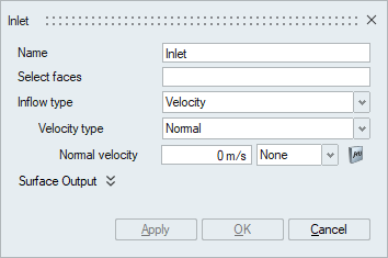
The Inlet panel is used to specify the inflow boundary condition for fluid flow simulations.
The Inlet panel has multiple options that can be specified, and the necessary options become available based on the solution setup defined in the Create Solution panel.
Laminar Flow Simulation
When the flow type under Physics in the Create Solution panel is set to Laminar then the following shown options become available to be defined in the Inlet panel.
- Select faces
The select faces option is used to select the faces/face groups of volume meshed bodies that should be specified with inflow boundary condition.
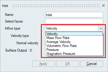
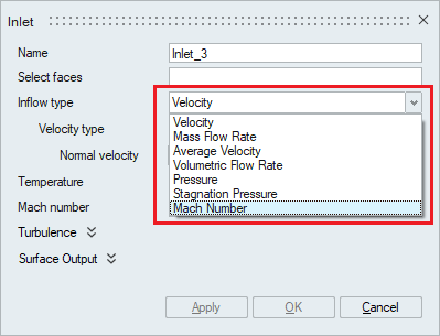
- Inflow type
The inflow type is used to specify the property with which the inlet boundary condition values would be specified. There are six inflow type available.
-
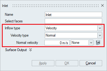
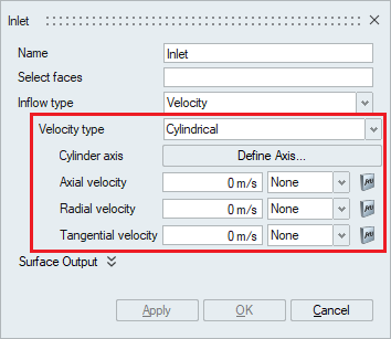
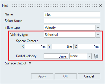
If Inflow type is set to Velocity, then the Velocity type is available for selecting the type of velocity that needs to be defined and accordingly the Velocity value should be input for the boundary condition to be specified.
The Velocity type can be set to Normal, Cartesian, Cylindrical, and Spherical based on the working coordinate system.
- If the Velocity type is set to
Normal which means that the
entering velocity vectors will be normal to the
faces/face group that is selected to be an Inlet. On
selecting the Normal velocity type, a Normal velocity
value must be provided. The Multiplier function is used
to scale the values or to specify the time varying
values.
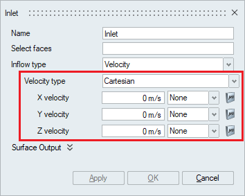
- If the Velocity type is set as
Cartesian, then the velocity
component values in the X, Y and Z directions should be
specified as an input. The Multiplier function is used
to scale the values or to specify the time varying
values.
- If the Velocity type is set as
Cylindrical, then the
cylinder axis should be defined using the Define Axis
option and the velocity component values in the Axial,
Radial and Tangential directions. The Multiplier
function is used to scale the values or to specify the
time varying values.
- If the Velocity type is set to
Spherical, then the
coordinates of the Sphere’s center should be defined
using the X, Y and Z options and the velocity value in
the Radial direction should be specified as an input.
The Multiplier function is used to scale the values or
to specify the time varying values.
- If the Velocity type is set to
Normal which means that the
entering velocity vectors will be normal to the
faces/face group that is selected to be an Inlet. On
selecting the Normal velocity type, a Normal velocity
value must be provided. The Multiplier function is used
to scale the values or to specify the time varying
values.
- If Inflow type is set to Mass
Flow Rate, then the Mass flux which is the rate
of mass flow per unit area should be specified as an input. The
Multiplier function is used to scale the values or to specify
the time varying values.

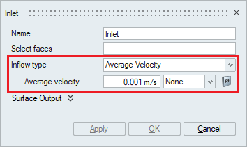
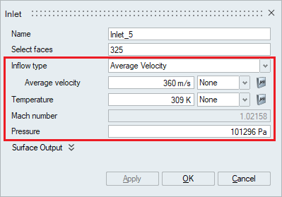
- If Inflow type is set to
Average Velocity, then an average
velocity should be input for the inlet boundary condition. The
Multiplier function is used to scale the values or to specify
the time varying values.
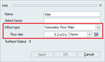
- If Inflow type is set to
Volumetric Flow Rate, then the Flow
rate which is the product of velocity and area should be
provided for the inlet boundary condition. The Multiplier
function is used to scale the values or to specify the time
varying values.
- If Inflow type is set to be
Pressure if inflow boundary condition
is based on the known pressure value at the boundary. It is used
when no flow rate is known, or if a flow rate is assigned at the
outlet.
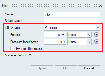
- The Pressure option is used to specify the static pressure value to which the inlet is exposed to. The Multiplier option is used to uniformly scale or specify the time varying static pressure value.
- The Pressure loss factor is used to specify a coefficient of pressure loss that will be added to or subtracted from the pressure boundary condition. The multiplier option is used to uniformly scale or specify the time varying pressure loss factor.
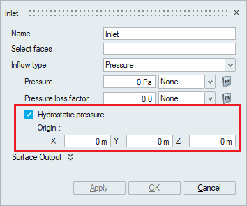
- Hydrostatic pressure is the
pressure that is exerted by a fluid at equilibrium
at a given point within the fluid, due to the force
of gravity. This option can be enabled to add the
hydrostatic pressure term to the overall pressure
boundary condition.
The coordinates of the origin of the body to which this flow boundary condition is assigned should be specified in the X, Y and Z options.
- If Inflow type is set to
Stagnation Pressure, then the total
or the stagnation pressure value should be specified for the
inflow boundary condition. Stagnation pressure is usually chosen
at the inlet when the pressure is driving the flow and the
pressure at the outlet is known. The Multiplier option is used
to scale the values or to specify the time varying
values.
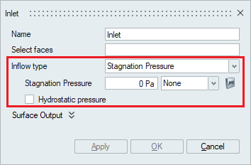
- Hydrostatic pressure is the pressure that is exerted by a fluid at equilibrium at a given point within the fluid, due to the force of gravity. This option can be enabled to add the hydrostatic pressure term to the stagnation pressure boundary condition.
-
Turbulent Flow Simulation
Depending on the turbulence model selected in the Solution panel, the Turbulence option in the Inflow panel will be updated.
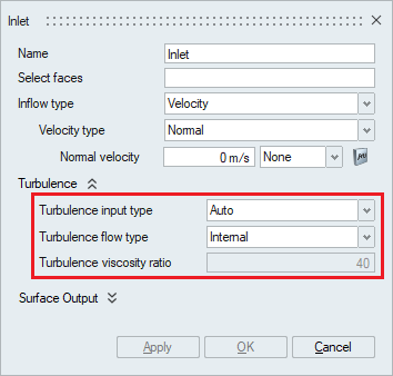
The Turbulence input type is used to specify the type of turbulence to be defined for the inflow boundary condition. Based on this selection the other turbulence options will be displayed.
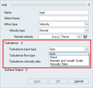
- When Auto is specified, the solver automatically takes
care of the turbulence based on the turbulence flow type. The turbulence flow
type is either internal flow or external flow based on the nature of the flow
being dealt with.
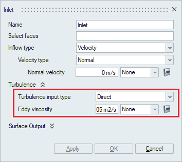
- The second option under turbulence input type is Direct.
If this option is selected, the Eddy viscosity value should be specified in case
the turbulence model being used is Spalart-Allmaras
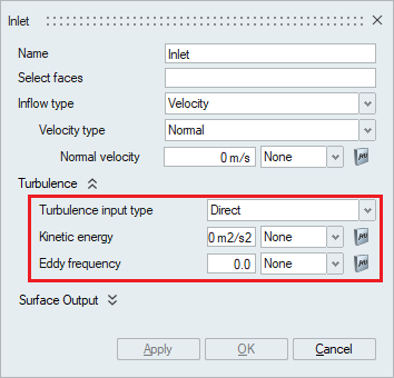
In case the turbulence model being used is Shear Stress Transport or K-Omega and the Turbulence input type is Direct then the Kinetic energy and Eddy frequency values should be specified.
Turbulence kinetic energy is the mean kinetic energy per unit mass associated with eddies in turbulent flow. The multiplier option can be used to uniformly scale the value or specify a time varying quantity.
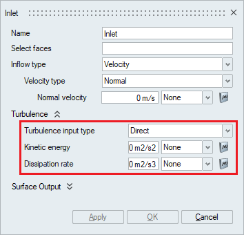
In case the turbulence model being used is Realizable K-Epsilon or Standard K-Epsilon and the Turbulence input type is Direct then the Kinetic energy and Dissipation Rate values should be specified.
Turbulence kinetic energy is the mean kinetic energy per unit mass associated with eddies in turbulent flow. The multiplier option can be used to uniformly scale the value or specify a time varying quantity.
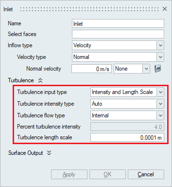
- The third option available under the turbulence input type is the
Intensity and length scale. This option can be used
when the turbulence intensity and the turbulent length scale is known.
- Turbulence intensity is defined as the ratio of
the standard deviation of the fluctuating flow velocity to the mean flow
velocity, and it represents the intensity of the flow velocity
fluctuations.
The turbulence intensity type option is used to specify the turbulence intensity value by either selecting a pre-defined value through choosing Auto, low, medium or high options or by selecting the Value option and typing in the desired intensity value.
- When either Auto, low, medium or high option is selected, the Turbulence flow type should be specified. The turbulence flow type is either internal flow or external flow based on the nature of the flow.
- Percent Turbulent Intensity
- For Auto turbulence intensity type, the percent turbulence intensity is 4.0% for internal flows and 0.1% for external flows.
- For Low turbulence intensity type, the percent turbulence intensity is 1.0% for internal flows and 0.1% for external flows.
- For Medium turbulence intensity type, the percent turbulence intensity is 4.0% for internal flows and 0.5% for external flows.
- For High turbulence intensity type, the percent turbulence intensity is 10% for internal flows and 1.0% for external flows.
- When the Value option is selected, the turbulence intensity value in percentage should be entered under the percent turbulence intensity option.
- Turbulent length scale is a physical quantity describing the size of the
large energy-containing eddies in a turbulent flow. The turbulent length
scale should normally not be larger than the dimension of the problem
and can be specified in the Turbulence Length
Scale option.
- Turbulence intensity is defined as the ratio of
the standard deviation of the fluctuating flow velocity to the mean flow
velocity, and it represents the intensity of the flow velocity
fluctuations.
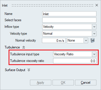
- The fourth option available under Turbulence input type is the
Viscosity Ratio or Intensity and Viscosity Ratio
based on the defined turbulence model.
- Turbulent viscosity ratio is the ratio between the turbulent viscosity and the molecular dynamic viscosity and can be specified in the Turbulence viscosity ratio option.
Atmospheric Inlet Flow Type
When the inflow type is set to Atmospheric, the inlet velocity profile and turbulence inflow quantities are generated automatically. Inlet velocity is prescribed via log law while inlet turbulence properties are computed according to the chosen turbulence model.
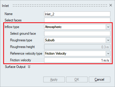
- Select ground face – Select a face which is typically a ground face.
- Roughness type - Type of the surface roughness for atmospheric boundary
layer. Provides typical terrain types and user specified input.
- Roughness height - Value of roughness height. Value can be specified for Roughness type “User Value”.
- Reference velocity type - Type of the reference velocity for atmospheric
boundary layer.
- Friction Velocity - Use ground friction velocity.
- Sample Height Velocity - Use height and corresponding velocity.
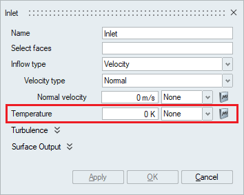
Turbulent Flow with Heat Transfer
When the Heat transfer option is enabled in the Solutions panel, the Temperature option becomes available in the Inlet panel. This option is used to define the temperature of the fluid this is flowing through the inlet faces/face groups. The multiplier option can be used to uniformly scale the value or specify a time varying quantity.
Compressible Flow Simulation
When the Compressible flow option is enabled in the Solutions panel, the mach number type is added under inflow type in the inlet boundary condition panel.
Mach number is a number representing the ratio of the speed of a body (such as an aircraft) to the speed of sound in a surrounding medium (such as air).
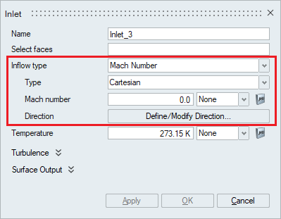
For the Volumetric and Mass flow rate inflow type , compressible flow simulation is not valid. For other types, mach number will be calculated automatically based on velocity and temperature and updated in the display.
If mach number exceeds 1.0, pressure option will be enabled to get the user input since all three variables (velocity, pressure, temperature) needed to specify supersonic inflow boundary condition.
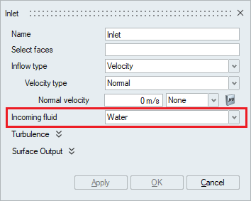
Immiscible Multiphase Flow Simulation
When the Multiphase flow option is enabled in the Solutions panel, the Incoming fluid type should be mentioned in the inlet boundary condition panel along with the inflow type and value.
Gravity Wave
If Inflow type is set to Gravity Wave, then it is used to define a wave boundary condition that generates a surface wave in a multiphase flow problem. This boundary condition overrides the velocity and field boundary condition.
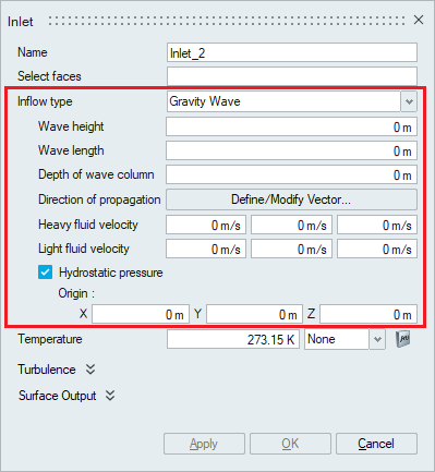
- Wave height - Defines the wave height or amplitude.
- Wave length - Defines the wave length.
- Depth of wave column - Depth of the wave column assumed where the wave is generated.
- Direction of propagation - Direction of propagation of the generated wave.
- Heavy fluid velocity - Velocity of the heavier fluid when used for a multiphase problem with two fluids and a stable interface.
- Light fluid velocity - Velocity of the lighter fluid when used for a multiphase problem with two fluids and a stable interface.
- Hydrostatic pressure - The pressure that is exerted by a fluid at equilibrium at a given point within the fluid, due to the force of gravity. This option can be enabled to add the hydrostatic pressure term to the overall pressure boundary condition.The coordinates of the origin of the body to which this flow boundary condition is assigned should be specified in the X, Y and Z options.
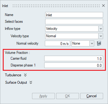
Disperse Multiphase Flow Simulation
When the Disperse Multiphase flow type is chosen in the Solutions panel, the Volume fraction option becomes available in the inlet boundary condition panel. The volume fraction of the carrier fluid and the volume fraction of the Dispersed phase should be mentioned appropriately.
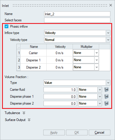
Eulerian Multiphase Flow Simulation
- If phasic inflow is active, both the carrier and disperse phases must be defined at the inlet. The inflow types supported are Velocity, Mass Flow Rate, Average Velocity and Volume Flow Rate types. In addition, Volume fraction type of Flux is supported for Phasic type. Up to five disperse fluids can be selected during the multiphase material definition.
- If phasic inflow is turned off, then the inlet definition takes the mixture velocity. The volume fractions of carrier and disperse phases will be provided in the Volume Fraction section.
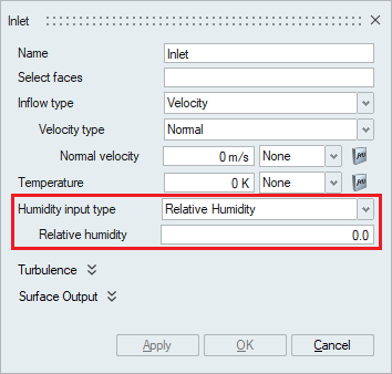
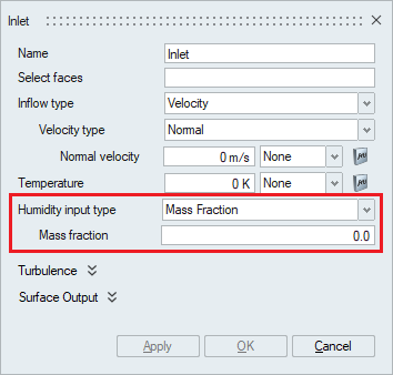
Humidity Simulation
Humidity is the concentration of water vapor present in the air. It can be defined as an inflow condition by specifying Relative Humidity, Dewpoint Temperature or Mass Fraction values.
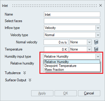
- Relative Humidity is the ratio of actual mass of water
vapor in air in the given space to the maximum mass of water vapor the air can
hold at the same temperature and pressure. It ranges from 0 to 1 and can be used
as the initial condition for Humidity.
- The Dewpoint temperature is the temperature at which the
air can no longer "hold" all of the water vapor which is mixed with it, and some
of the water vapor must condense into liquid water. The dew point is always
lower than (or equal to) the air temperature. The dewpoint temperature can be
prescribed as an inlet condition for Humidity.

- Mass fraction is the ratio of the mass of the phase of
fluid of interest (water vapor or air) to the total mass of mixture. The mass
fraction can be prescribed as an inlet condition for Humidity.
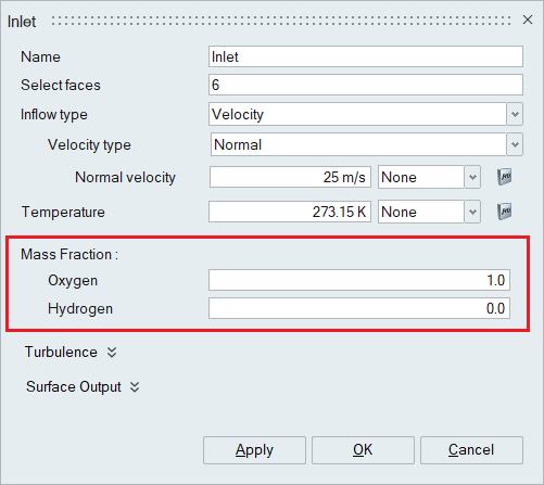
Gas Kinetics Multiphase Flow Simulation
When the Gas Kinetics Multiphase flow type is chosen in the Solutions panel and the appropriate Gas Kinetics material is assigned to bodies in the Solution, the Mass fraction option becomes available in the inlet boundary condition panel. The mass fraction of the selected gases should be mentioned appropriately.
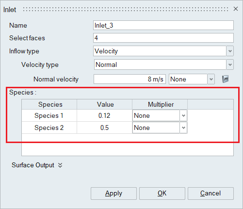
Species
When the number of species is specified in the Solutions panel, the Species option becomes available in the inlet boundary condition panel. The species value should be mentioned appropriately.
Surface Output
These advanced options do not affect the results of the solution but defines the way the results are output.
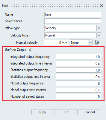
- Integrated output frequency
Time step frequency at which the integrated surface quantities are output. If zero, this option is ignored.
- Integrated output time interval
Time frequency at which the integrated surface quantities are output. If zero, this option is ignored.
- Statistics output frequency
Time step frequency at which the statistics of surface nodal quantities are output. If zero, this option is ignored.
- Statistics output time interval
Time frequency at which the statistics of surface nodal quantities are output. If zero, this option is ignored.
- Nodal output frequency
Time step frequency at which the surface quantities at the nodes of the surface are output. If zero, this option is ignored.
- Nodal output time interval
Time frequency at which the surface quantities at the nodes of the surface are output. If zero, this option is ignored.
- Number of saved states
Number of solution steps to retain on the disk. If zero, all the solution steps are retained.