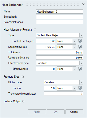
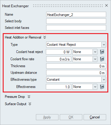
Heat Exchanger
![]()
Introduction
Typically, heat exchanger geometry is quite complex with large number of plates and pipes, and therefore it is not realistic to model the actual heat exchanger when performing system level simulations. In such scenarios, a simplified approach can be employed where only the effect of the heat exchanger on the cross flow is considered instead of modeling the actual heat exchanger. This is done using Heat Exchanger Component panel.
- Heat Addition or Removal
- Pressure Drop
Select Body
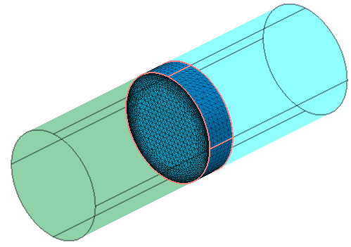
The body to be modeled as heat exchanger is selected. Once the body is selected, all other bodies will automatically be made transparent to conveniently select the faces of this body. In the below example, middle pipe body is selected as heat exchanger and automatically the first and last bodies becomes transparent.
Select inlet faces
Specifies the inlet face of heat exchanger body. The direction of flow will be automatically computed. In the figure below, the X normal face is selected as the inlet face and hence the solver will interpret the flow in the positive X direction.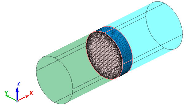
Heat Addition or Removal
-
Type
Specifies the heat input type. This can be done in 2 ways:
- Coolant Heat Reject
- Coolant Temperature
Based on the option selected, the panel gets updated to take the appropriate inputs. If Coolant Heat Reject is selected, Coolant heat reject value is required. The Coolant heat reject value can also be scaled using a Multiplier Function. If Coolant Temperature is selected from drop down, Coolant temperature value is required. The Coolant temperature value can also be scaled using a Multiplier Function.
-
Coolant flow rate
Specifies the volumetric flow rate of the coolant in the heat exchanger.
-
Thickness
Specifies the thickness of the heat exchanger body, which is the distance from the inlet face to outlet face of heat exchanger.
-
Upstream distance
This is the distance in front of the heat exchanger inlet surface at which the upstream temperature is sampled.
-
Effectiveness Type
The effectiveness of a heat exchanger is defined as the ratio of the actual heat transfer to the maximum possible heat transfer. This option is used to specify the type of the thermal effectiveness value to be mentioned.
If the effectiveness type is set to Constant, then a constant value of effectiveness for the heat exchanger should be provided. By default, the value is 1 which indicates 100% thermal effectiveness.
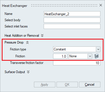
Pressure Drop
The pressure-drop across the heat exchanger, in the axial direction is given by:

where ƒ is the friction factor; ρ is the density; u is the axial velocity at the minimum cross-section area. The friction factor should be specified for the pressure-drop to be calculated.
- Friction Type
Specifies the type of the friction factor model used in the simulation. The friction type can be a constant, Kays-London or Piecewise Linear.
- Constant Friction Type
When the friction type is set to constant, then a constant value of friction should be specified. A constant friction factor applies a spatially constant friction factor.
- Kays-London Friction Type
The Kays-London friction factor is given by,
ƒ = ƒinlet − ƒoutlet + ƒcore
where ƒinlet, ƒoutlet and ƒcore are the inlet, outlet and core frictions respectively.
In order to calculate these quantities, certain inlet and outlet loss coefficients should be provided by the user along with the values shown in the panel below,
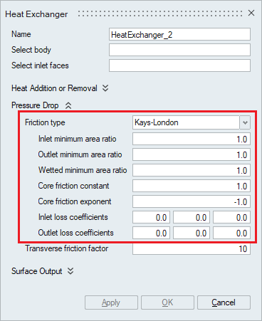
- Inlet minimum area ratio
Specifies the ratio of inlet area to the minimum flow area.
- Outlet minimum area ratio
Specifies the ratio of outlet area to the minimum flow area. This typically is equal to Inlet minimum area ratio.
- Wetted minimum area ratio
Specifies the ratio of the wetted area to the minimum flow area.
- Core friction constant
Specifies the constant coefficient of the core friction factor.
- Inlet loss coefficients
Specifies the loss coefficients for the inlet friction factor. This is a 3-component array corresponding to the constant, linear, and quadratic coefficients.
- Outlet loss coefficients
Specifies the loss coefficients for the outlet friction factor. This is a 3-component array corresponding to the constant, linear, and quadratic coefficients.
- Inlet minimum area ratio
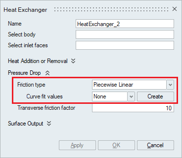
- Piecewise Linear Friction type
The Piecewise linear friction type takes in the Piecewise linear values in the form of a table which can be imported or created. The pre-existing tables can be selected using the drop-down option and a new table could be created using the Create option.
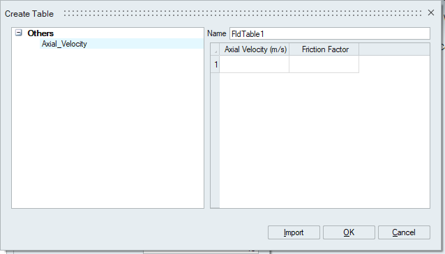
Create table panel is where the values could be typed in or a table could be imported by clicking on the import option. The Name option is used to rename the table containing the Piecewise Linear values. As shown below, the table consists of two columns. First column is Axial Velocity in the working units and the second column is the corresponding Friction Factor value. A new row can be created by clicking on one of the rows and hitting enter from the keyboard.
When using the import option, the table should be only in the form of .csv, .dat or .txt file. The table importing need not contain any column names as the values are being imported to a predefined column.
- Transverse friction factor
Specifies the fraction of the friction factor used for the transverse friction factor. Higher values yield higher degrees of unidirectional flow but comes at the expense of stability. By default, the value is 10.
- Constant Friction Type
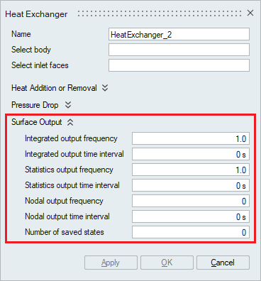
Surface Output
These options provide controls on the frequency, time interval outputs along with the number of saved outputs.
-
Integrated output frequency
Time step frequency at which the integrated surface quantities are output. If zero, this option is ignored.
-
Integrated output time interval
Time frequency at which the integrated surface quantities are output. If zero, this option is ignored.
-
Statistics output frequency
Time step frequency at which the statistics of surface nodal quantities are output. If zero, this option is ignored.
-
Statistics output time interval
Time frequency at which the statistics of surface nodal quantities are output. If zero, this option is ignored.
-
Nodal output frequency
Time step frequency at which the surface quantities at the nodes of the surface are output. If zero, this option is ignored.
-
Nodal output time interval
Time frequency at which the surface quantities at the nodes of the surface are output. If zero, this option is ignored.
-
Number of saved states
Number of solution steps to retain on the disk. If zero, all the solution steps are retained.