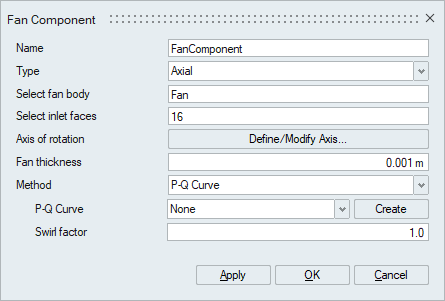
Fan Component
![]()
This option is used to setup a lumped fan model on a body. This is used to simulate effects resulting from a fan without using moving reference frame or rotational mesh motion.
Description
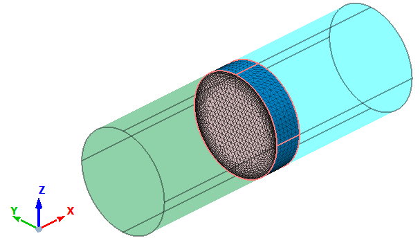
- Select Body
The body to be modeled as fan component is selected. Once the body is selected, all other bodies will automatically be made transparent to conveniently select the faces of this body. In the below example, middle pipe body is selected as fan component and automatically the first and last bodies becomes transparent.
Note: Only one body selection is allowed.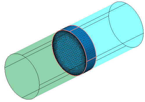
- Select inlet faces
Specifies the inlet face of fan component body.
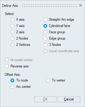
- Define Axis
Define the axis of rotation for the fan using Define Axis. Center of the fan component can be automatically calculated based on this axis.
- Fan Thickness
Specify the Fan thickness for the lumped fan model.
The fan component can be defined by two methods,
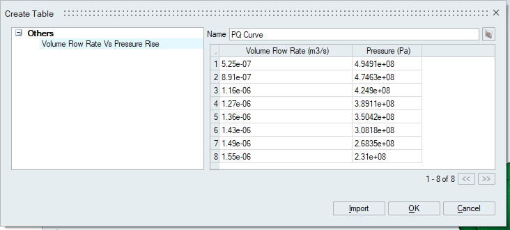
- P-Q Curve
Type of the fan pressure-flow rate (P-Q) performance curve to simplify the fan modeling process. You can specify fan performance directly through P-Q curve, by-passing the legacy approach of non-dimensional coefficient calculations.
A table can be created which defines the fan performance curve with the first column of flow rate and the second column of pressure increase.
- Coefficients
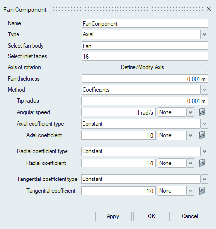
Tip radius
Specify the Tip radius for the lumped fan model.
Angular Speed
Specify the fan rotational speed. A multiplier function can be used for scaling the angular speed.
Coefficients
A fan component is modeled by adding axial, tangential, and radial forces to the momentum equations. These associated coefficients appear in the momentum equation as follows:
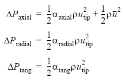
These coefficients can be defined in 2 ways:
- Constant
Enter a constant value for the coefficient across the entire body.
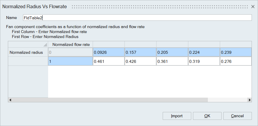
- Piecewise Bi-Linear
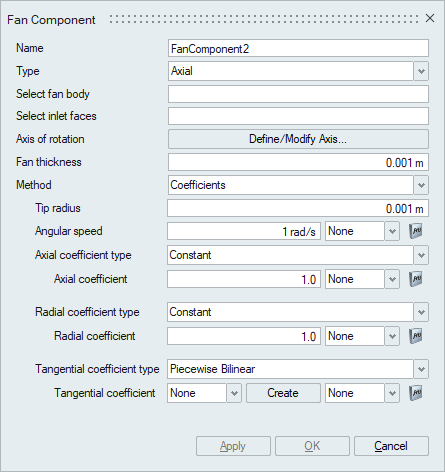
A table can be created to capture the change in the coefficient across the radius of the Fan Component body for different flow rates. A sample table is attached in the picture below.
- Constant
- P-Q Curve