Create Verity Weld Sets
![]()
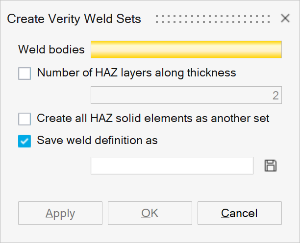
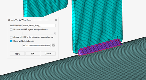
This tool is used to create set information required for verity weld fatigue solver. Solid element and node set will be created for the given weld bodies.
There are five sets will be created for one toe side of weld body.
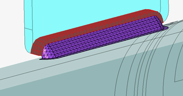
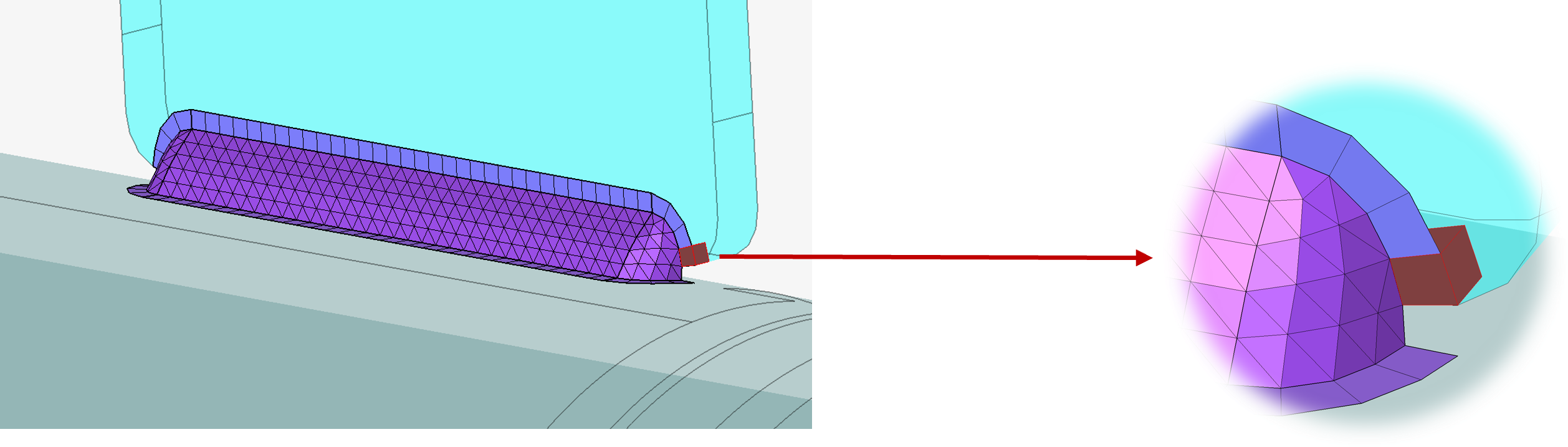
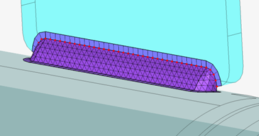
- One layer of HAZ elements next to Weld body.
- Starting solid element in the HAZ.
- Weld body toe nodes as weld line path.
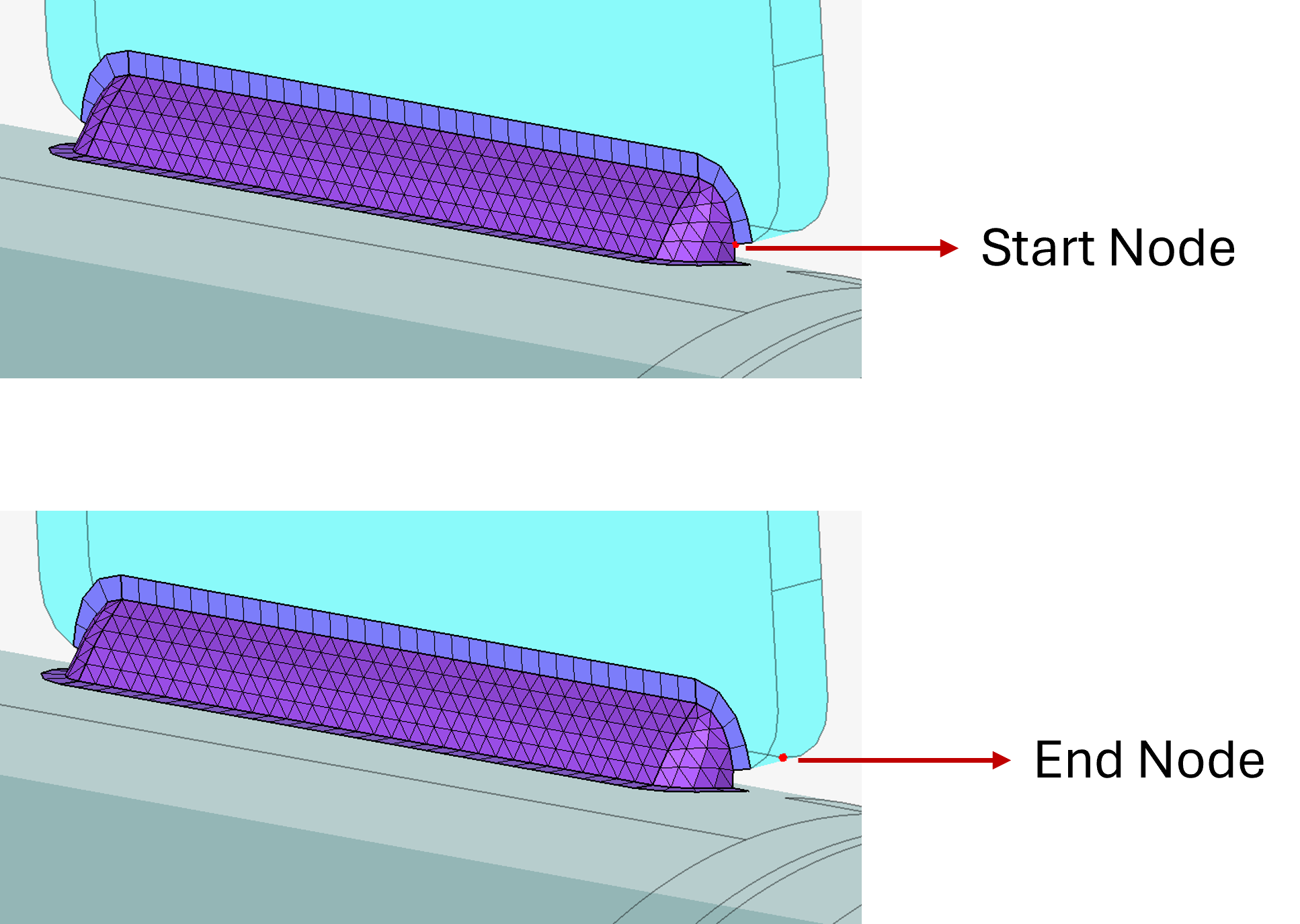
- Starting node of weld line path.
- End node along the thickness of weld connected body corresponding to starting node.
It will also write a weld definition file in which the HAZ solid element ids, weld line path node ids and other information required for Verity solver.
Input
Output
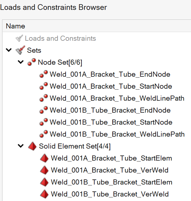
Name Convention: Weld_001A_Bracket_Tube_VerWeld
001 -> weld number (for this body pair)
A or B -> two toes of weld body (Toe A or Toe B)
Bracket -> Body connected by this weld
Tube-> Body connected by this weld
Ver Weld (HAZ elements)
Start Elem (start solid element)
Weld Line Path
Start Node and End Node (Last Node along thickness)
Weld Definition file Example
Solid element ids and node ids are written in the format below along with some more information required for Verity.
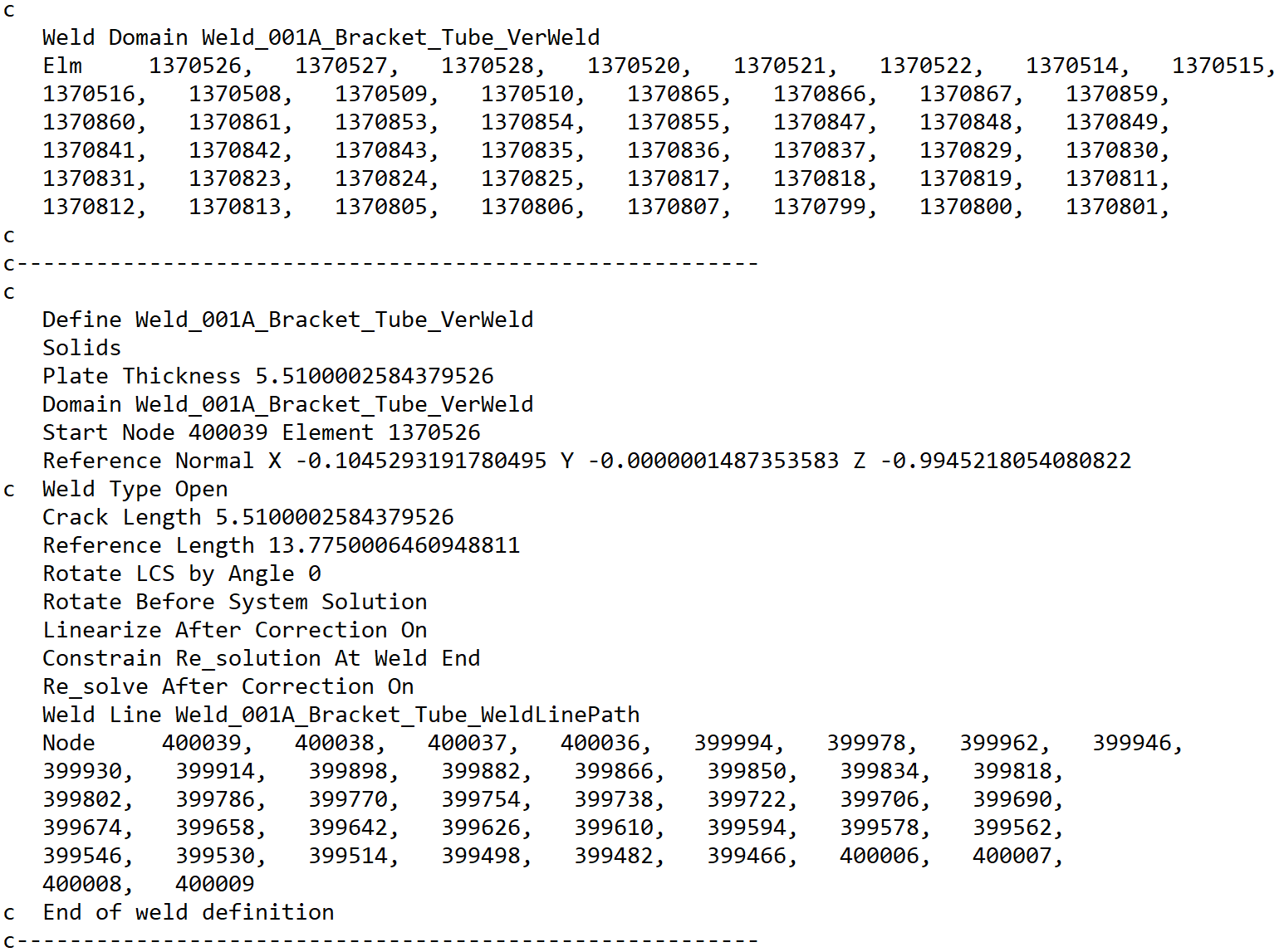
Plate thickness and crack length are distance between start node and end node.
Reference length is 2.5 times Crack length.
Reference normal is vector between start node and end node.
- Set will be created only when weld connected HEX mesh body with one layer of HAZ next to welds.
- Following are the three different cases of weld being considered for
creating sets. Weld connected to
- Two HEX mesh bodies,
- One HEX mesh body and one TET mesh body,
- One HEX mesh body.
- Multiple welds can be given as input in one go.
-
Solid elements are collected all layers along thickness by default.
If user wants to collect only certain number of layers along the thickness, then choose “Number of HAZ layers along thickness” and enter required layers.
- Option to create all the weld HAZ elements in one set.