CAD Error Check
Introduction
Design of components using a CAD system can result in a CAD model which can cause difficulties for downstream applications such as meshing, analysis and manufacturing. These design flaws can result in expensive fixes to the model and delay in getting the product to market. By identifying and eliminating the design errors when the model is being designed, significant cost benefits can be achieved.
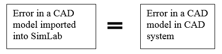
SimLab has direct access to CAD models designed in ProE and Parasolid and therefore there is no loss of data in reading a CAD model into SimLab.
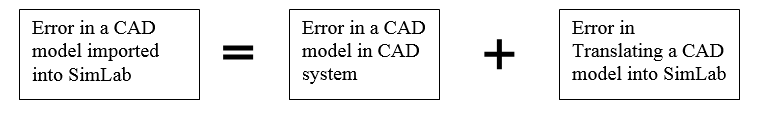
There is no translation error and so the errors one sees in a CAD system is the same as they would in SimLab.
Error Definition
The different types of errors that can be identified are defined.
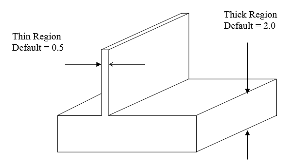
Thick / Thin regionA thick region is where 2 surfaces are close to each other. If we fit a ball inside this region, it will touch the 2 faces. The radius of the ball is the thickness at this location. Default values of 0.5 and 2.0 are used for Thin and Thick region identification.
 Narrow step
Narrow step is where there is a thin surface and the 2 adjacent faces are almost perpendicular to it.
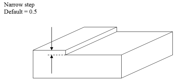
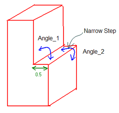
80 < Angle_1 < 100 and 80 < Angle_2 < 100. A tolerance of 10 deg is used when detecting the narrow steps.
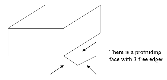
Free edgesFree edges are rare in CAD models. But if they do appear, they can be detected.
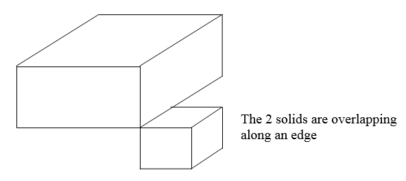
 Overlapping edges
Overlapping edges are also rare in CAD model and can be identified if any.
 Overlapping
faces
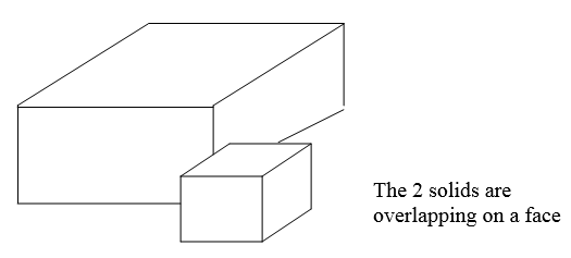
Overlapping
facesThe surface overlap can be between 2 solids or it can happen within the same solid. Both cases will be identified.
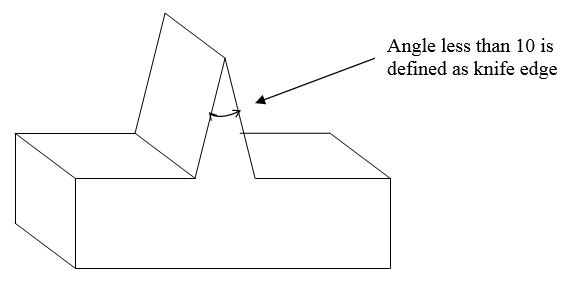
 Knife
edge
Knife
edgeThis is a very common error and can be difficult to identify visually.
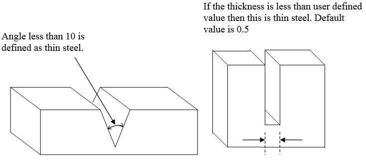
 Thin steel
This steel are of 2 types. Once is the reverse of a knife edge. The other is the case where there is a cut out as shown below.
 Sharp
corners
Sharp
cornersSharp corner is like a knife edge and a thin steel but the angle between the 2 faces should be between 10 and 30 degrees.
UndercutTo identify undercuts, a normal is defined by selecting a plane and a distance is specified. If there exists another surface which satisfies the following conditions
- Its distance is less than user defined distance.
- The normal to the face is pointing opposite to the normal to the user defined normal. In other words the angle between the normal should be between 90 and 180 degrees. To avoid numerical errors, an angle between 100 and 180 degrees is recommended.
CAD Error Check Module
Select Advanced > CAD Error Check. All operations required for CAD error check is captures in this module. If this option is not available, then check to see if the license for CAD Error Check application is available.
The process of identifying the CAD errors can be broken into the following steps:
- Define what errors to be identified and what the parameters should be
- Identify the errors
- Display the errors on the screen
- Generate a report on the errors
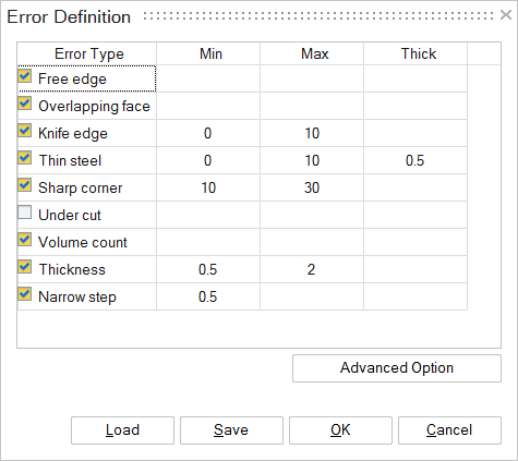
After importing the CAD model, the next step is to select the errors to be identified and set the parameters that define a specific error type.
When the Undercut error type is selected, a base face has to be selected. The undercut surfaces will be found based on this base face.
The check-box in front of the error types can be used to identify or not to identify that error in the model.
Once the error types and parameters are set, the user can save the “Error Definition” in a file. This can be imported again at a later time.
Mesh size is important to identify the errors. In default, it will take it from max thickness value. But user can change this by using “Advanced option” button.
Identify ErrorsThe selection of “Identify Errors” will start the process to identify the errors. If there is a part file it will identify the errors for this part file. If there is an assembly and no part file is selected, it will then identify the error for the entire assembly. If there is an assembly and one part file is selected, it will only identify the errors for that part file.
Display ErrorsAfter the CAD errors are identified, the number of errors of each type is listed. For the sample model “cad_error_check_sample.prt.1” file, the number of error of each of the error types is shown below.
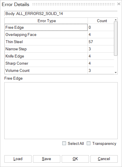
By selecting each of the error types, the user can display the errors on the screen. For example, if the user selected ‘Knife Edge” in the “Error Details” dialog box, then the display changes to
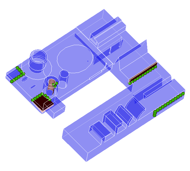
Where the error locations are represented by green spheres and the surfaces adjacent are highlighted.
One can display a specific error by unchecking the Select All check box and selecting the ones the second list. This will zoom to the specific error. The zoom factor will be that in the current display. Once the user zooms into a location, then the further selection of the individual errors will be based on this zoom factor
The error details can be saved and opened at a later time. For the errors to be displayed, the CAD model should be present.
Write ReportThis will generate an html file which will have:
- Error Definition
- Error Summary
- A screen shot of all the errors