Auto Extrude
![]()
Description
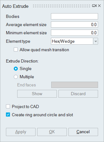
This tool is used to create Hex mesh automatically for electronic chips and components. It provides one click solution for components wherein the user has to select the bodies and specify the size for Hex meshing.
Element type1.Hex/Wedge
2.All Hex (Used to generate complete hex meshed bodies)
3.Wedge6
4.Tet4
Allow quad mesh transition
This option generates quad mesh with transition. For more details please refer Allow Quad Mesh Transition.
Extrude Direction- Single:This option is used for bodies with all the components extruded along the same direction.
- Multiple: This option is used for bodies with the components extruded in multiple directions. Show option identifies the end faces automatically and user can review and edit the selection manually.
Project to CAD
This option is used to project the nodes of the output bodies onto the corresponding CAD entity. For more details please refer Project to CAD.
Create ring around circle and slot
This option will create one or two layers of elements around circles and slots. For more details, please refer Create ring around circle and slot.
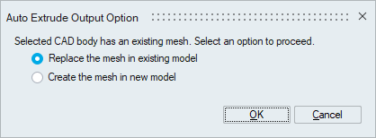
Auto extrude output option for different inputs- FE Body: The output mesh will be created in a new model.
- CAD Body: The below dialog will prompt the user to select the output location if an equivalent mesh is already present. For more details, please refer Mesh output options for CAD body.
- Edge mesh control is supported for auto extrude – single option. Users can control the mesh on edges that aren't oriented in the thickness direction by applying edge mesh control. For more details, please refer Edge Mesh Control.
- Auto extrude – single option is enhanced to create quad pattern for disc faces in the output.
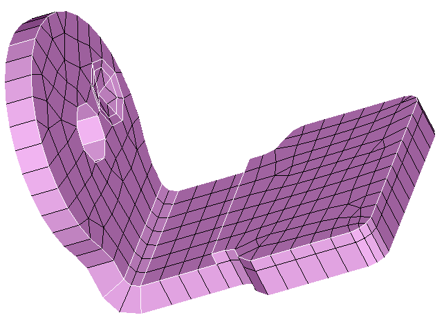
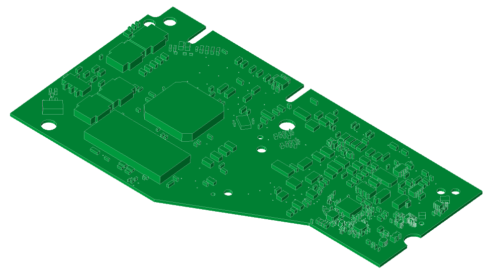
Example 1
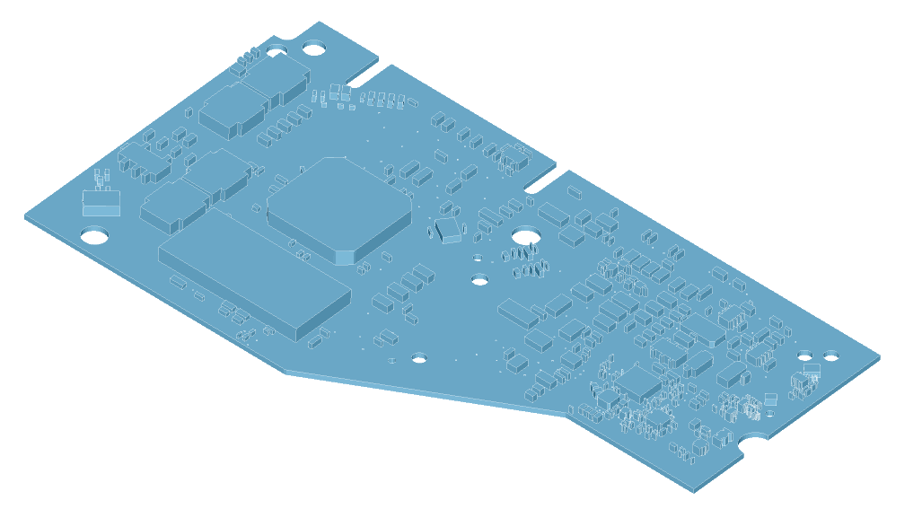
Single option is used for meshing the component extruded along the same direction.Input
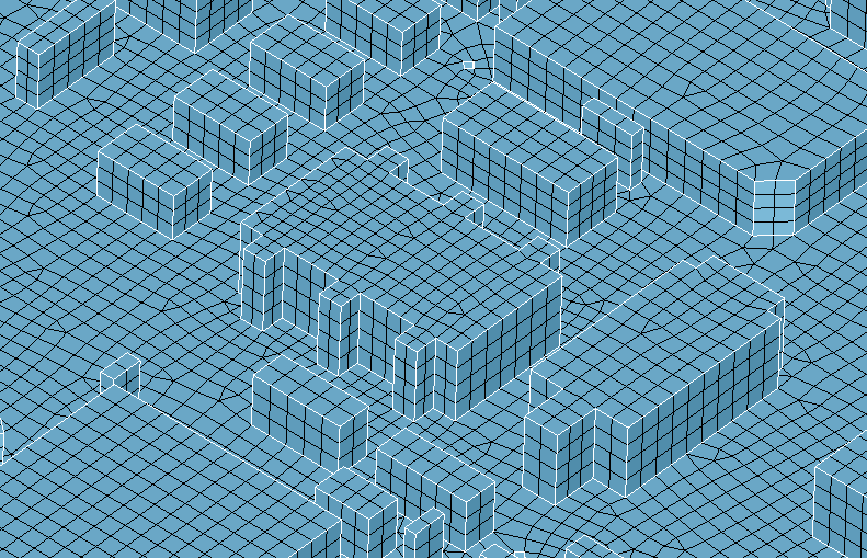
Output
Example 2
Multiple option is used for meshing the components extruded along different directions.Input
Output