2.5D Hex Mesh
![]()
Description
The global parameters to mesh a body with volume elements (Wedge/Hex) is specified using the 2.5D Hex Mesh dialog. The list of solid element types supported are,
- Wedge6
- Hex8
The parameters for Hex and Wedge is shown below.
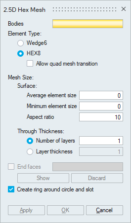
"Allow quad mesh transition" option generates quad mesh with transition. For more details please refer Allow Quad Mesh Transition.
Surface- Average element size: Defines the average element edge length for the mesh on the surface.
- Minimum element size: The mesh will have no elements with an edge length smaller than the minimum element size.
- Aspect ratio: The quality of mesh can be controlled by setting the Aspect ratio.
- Number of layers: It specifies the desired number of layers along the thickness direction.
- Layer thickness: It specifies the layer thickness along the thickness direction.
If the tool fails to identify the end faces for the given body, hex mesh cannot be created. In this situation user can give the end faces to generate hex mesh.
Show option identifies the end faces automatically and user can review and edit the selection manually. User can clear the end faces using discard option.
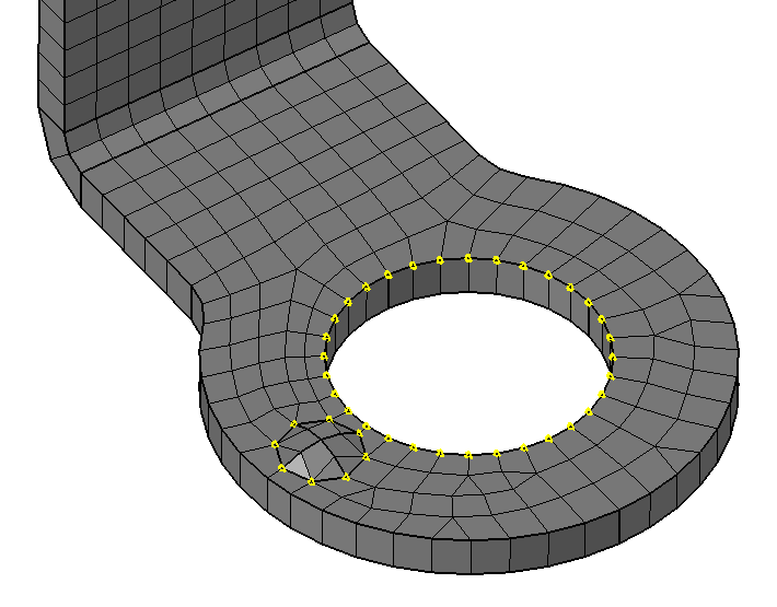
Create ring around circle and slotThis option will create one or two layers of elements around circles and slots. For more details, please refer Create ring around circle and slot.
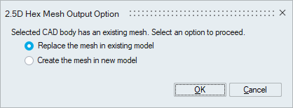
2.5D hex mesh output option for different inputs
- FE Body: The output mesh will be created in a new model.
- CAD Body: The below dialog will prompt the user to select the output location if an equivalent mesh is already present. For more details, please refer Mesh output options for CAD body.
Edge Mesh Control
Users can control the mesh on edges that aren't oriented in the thickness direction by applying edge mesh control. For more details, please refer Edge Mesh Control.
Washer Mesh Control
Users can create rings around a circle by applying washer mesh control. For more details, please refer Washer Mesh Control.
Volume Layer Mesh Control
Users can control the number of layers along the thickness direction by applying volume layer mesh control. For more details, please refer Volume Layer Mesh Control.
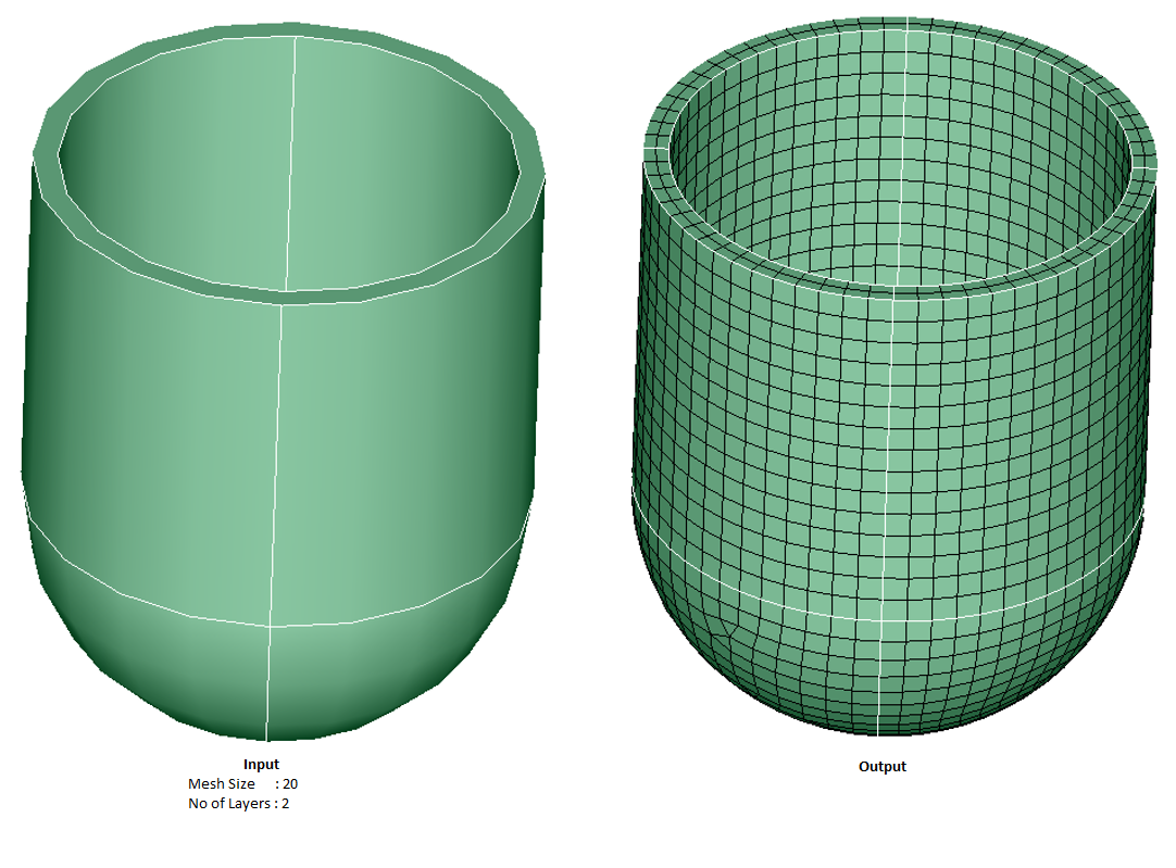
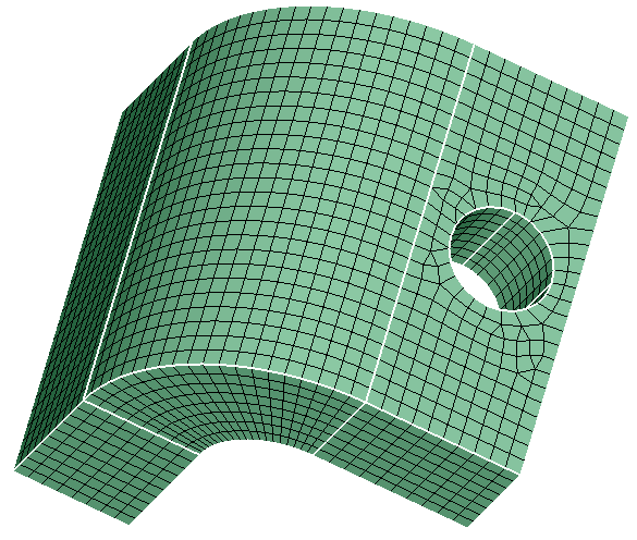
Example 1
Example 2: End face input
Input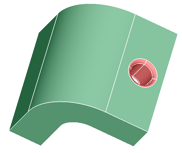
Output
Example 3: Edge mesh control input
Input
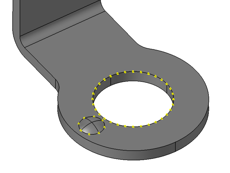
Output