Polarity Mark
For components that should have a polarity mark, check the marks validity on design.
The Polarity Mark dialog contains the following
sections:
- Target Component Definition
- Component Group Selection: Select the target component group from the component group list.
- Target Layer Definition: Select the polarity mark layer.
- Top/Bottom Mark Layer: If polarity marks are designed on a specific layer, define them from the layer list.
- Polarity Mark Definition: Select the shape of the Polarity Mark. Allowable
polarity mark types in PollEx DFM are shown in
Figure 1. If the following types of polarity marks are detected
in searching area, PollEx DFM recognizes that the
component has a polarity mark.
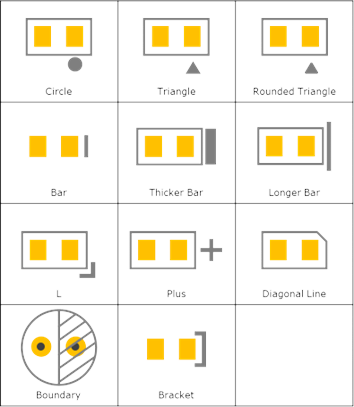
Figure 1.- Check Polarity with Text Strings: If polarity marks are used as text strings, describe used text strings. For example, 1 A A1 A2. Delimiter is space.
- Checking
- Check Polarity Mark with Board Silkscreen: If the polarity mark does
not belong to a footprint but to board figure geometries, use this
option.
- Searching Distance from Component Outline: If other board
figure geometries are used as a polarity mark, specify
searching distance from the component contour.
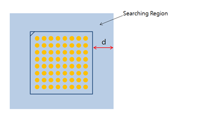
Figure 2.
- Searching Distance from Component Outline: If other board
figure geometries are used as a polarity mark, specify
searching distance from the component contour.
- Check Polarity Mark with Board Silkscreen: If the polarity mark does
not belong to a footprint but to board figure geometries, use this
option.
- Polarity Mark Overlapping Check
- Overlapping with Silkscreen: Check if the polarity mark overlaps with another silkscreen.
- Overlapping with Pad: Check if the polarity mark overlaps with another component pad.
- Overlapping with Via Hole: Check if the polarity mark overlaps with via hole.
- Overlapping with Board Figure Hole: Check if the polarity mark overlaps with a board figure hole.