Component Spacing2
Check the clearance between the components-based placement directions.
The Component Spacing2 dialog contains the following sections:
Component Clearance
- Add New Target Component Groups: Use this menu to add new checking items
into the clearance table. Add combinations with the component group and
clearance type settings, and PollEx DFM will
automatically create necessary clearance tables. For example, if a new
target group combination with two groups is added, A and B, PollEx DFM will create three combinations.
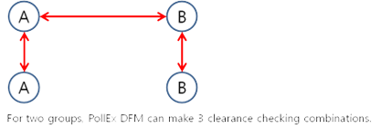
Figure 1.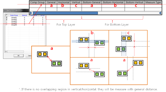
Figure 2. - Soldering Direction Definition: Input the soldering direction of the board.
Detect the soldering direction by analyzing the mark component or by
defining the direction manually.
- Component Group: Select a component group used for analyzing the
soldering direction and defining the library direction. The library
direction is the 0° direction of the mark component. For example,
the direction mark is registered as
 or 0° into the footprint library, then
placed in that fashion in the board. In this case, the library
direction is Left to Right. In some cases, the direction mark is
registered as or 0° into the footprint library, then
placed as
or 0° into the footprint library, then
placed in that fashion in the board. In this case, the library
direction is Left to Right. In some cases, the direction mark is
registered as or 0° into the footprint library, then
placed as  or 90°. In this case, the library
direction is Left to Bottom.
or 90°. In this case, the library
direction is Left to Bottom. - Library Direction
- Soldering Direction: Input either horizontal or vertical as the soldering direction. After setting the soldering direction, define the placement direction of each component. Any component placed in a different way from the set direction is detected as an error.
- Component Group: Select a component group used for analyzing the
soldering direction and defining the library direction. The library
direction is the 0° direction of the mark component. For example,
the direction mark is registered as
- Clearance Table: Once clearance checking combinations are added into a
clearance table, the same item will be applicable for top and bottom. An
input line has the following rule columns:
- Item: Item name.
- Group1: First component group.
- Measure1: First component groups measurement base type.
- Group2: Second component group to be measured with group1.
- Measure2: Second component groups measurement base type.
- SMT Direction
- None: Ignore SMT progress direction.
- Horizontal: SMT direction horizontal.
- Vertical: SMT direction vertical.
- Top General, Top-A, Top-B, Top-C and Top-D: Top side measure type.
- Bottom General, Bottom-A, Bottom-B, Bottom-C and Bottom-D: Bottom side measure type.
- Options:
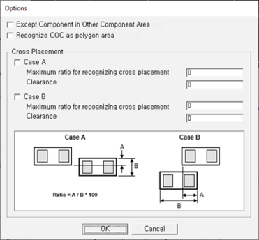
Figure 3.- Except Component in Other Component Area: Each lines exceptional option. When it is checked, PollEx DFM will skip clearance checking for overlapped components.
- Recognize COC as polygon area: When the measure base is set to COC or COC+Pad, this option recognizes the COC as a polygon area.
- Cross Placement:
- Case A: Check horizontal cross placement.
- Maximum ratio for recognizing cross placement: Set the maximum ratio for recognizing cross placement.
- Clearance: Set the clearance between cross placed components.
- Case B: Check vertical cross placement.
- Maximum ratio for recognizing cross placement: Set the maximum ratio for recognizing cross placement.
- Clearance: Set the clearance between cross placed components.
- Recognize conductive figure shape as Pad: Recognize an object that is drawn with the figure shape in the conductive layer as a pad.
- Keep Other Values While Adding new Classes Combination: While adding a new component class combination, PollEx DFM will keep previous values.
- Exclude Checking for SMD Pins, not having Metal Mask: PollEx DFM will skip checking for SMD components that do not contain pins with metal mask data.
- Exclude Checking for Components, having different Property Value: After
checking component property value, if their property value is different than
the given property value, PollEx DFM will skip them
during checking.
- Property: Click
 button to select
property, then the selected property value will be displayed in the
input field.
button to select
property, then the selected property value will be displayed in the
input field.
- Property: Click