Results Data
You can export specific data collected during your simulation for analysis using general settings or queries.
- Navigate to .
-
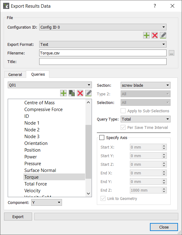
In the Export Results Data dialog box, specify the
following details:
For Specify Configuration ID Click the  icon to create a new
Configuration ID.
icon to create a new
Configuration ID.You can create multiple queries for a model within a single configuration or multiple configurations. For example, one configuration may contain a number of queries relating to particles while it may have queries solely relating to contacts. You can modify configurations at any point, add new queries, or remove redundant queries.
Export Format Select the export file format - EnSight (.case) or Text (.csv). For EnSight files, and ensure that the total number of characters (file name and directory) is not greater than 72. Filename Specify a file name and location for the configuration. Title Specify a title for the configuration.
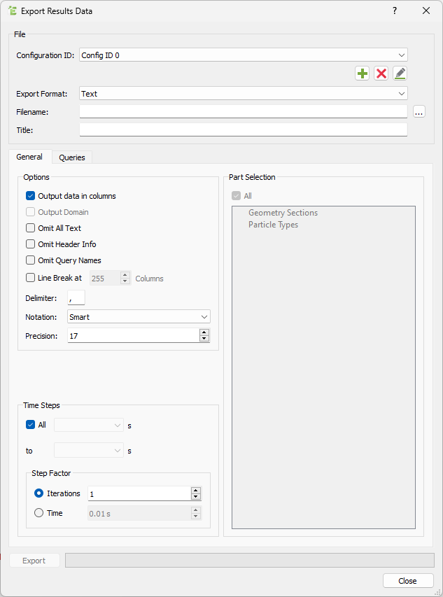
Export Data - General
You can configure general settings for exporting results data.
| For | Specify |
|---|---|
| Output Data in Columns | Indicates how data is laid out in the exported file.
Select the checkbox to extract the data in columns.
The following images show a sample of the same
exported data. 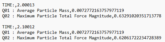 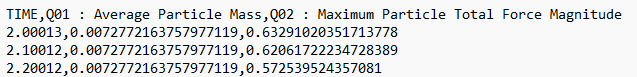
|
| Output Domain | Select the checkbox to export data to an EnSight file. The information on the domain will be exported with the data. Else, a new domain will be created automatically when the file is loaded in EnSight. |
| Omit All Text | Select the checkbox to extract data without the
Header Info, Query Names, or data labels in the exported
file. The following figure shows an example of exported
data with Omit All Text and Output Data in Columns
turned on: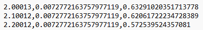
|
| Omit Header Info | Select the checkbox to extract data without the
Header Info. Header Info contains information about the
query which was output but the file can be easier to
parse in a post-processing operation if this data is
excluded from the file. The following image shows an
example of exported data with Header Info: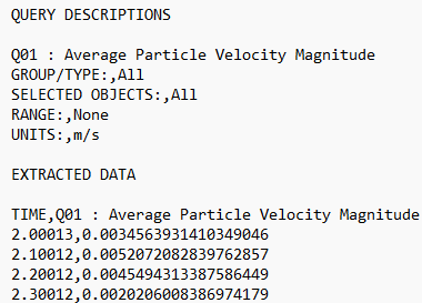 |
| Omit Query Names | Select the checkbox to extract data without the Query
Names included in the data labels. The following image
shows an example of exported data without Query
Names: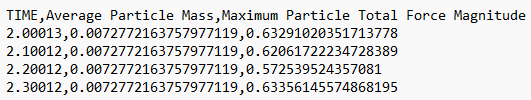 |
| Line Break | Select the checkbox to start a new line after X columns. |
| Delimiter | Select the checkbox to set a delimiter if you are exporting to a text file. By default, EDEM inserts a line break at 256 columns (the maximum allowed by Microsoft Excel). |
| Notation | Specify the notation used in your exported data
files. Options are:
|
| Precision | Specify the precision of the exported data files.
Note: You can change the
precision at the export stage or navigate to if you want to modify the default for
all subsequent exports. |
| Time Steps | Select All to extract data from all Time Steps in your simulation or from a defined range. If a Time Step is from a partial save (indicated by the Time Step being disabled), data for the selected attributes may not be available. This is indicated by N/A in the exported file. |
| Step Factor | Specify the Step Factor to extract data at a certain frequency despite the simulation deck containing more write-out points. |
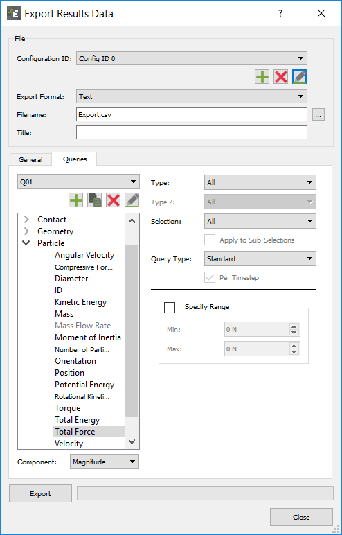
Export Data - Queries
You can also use queries to export the results data. A configuration can contain multiple queries, each of which defines one data attribute. Queries define what information is exported.
-
Click the Queries tab to add a new query or remove
redundant queries.
A query is used to define a single element attribute. For example, a query could be up to extract the x-position of particles of type A in your model.
-
In the Export Results Data dialog box, click the
Queries tab and click the icon to create a new query.
The attributes that you can export are listed under the element they are related to (collisions, contacts, particles, or Geometry). For more information about all the available attributes, components, and query types, see Attribute Definitions. - Select the Apply to Sub-Selections checkbox to export a separate query for each bin in a group (if defined), rather than one combined query for the entire group.
-
Click any attribute to select it and then select the component of that
attribute.
For example, the magnitude of a contact vector. All available attributes and their components are listed in the following tables.
-
Select the query type from the Query Type dropdown
list.
The query type is used to determine which data values will be exported for a particular attribute. For example, if a query has been set up to export the velocity of particles of type A, you can select to export the maximum, minimum or average velocity per Time Step.The following data is exported for each query type:
Query Type Data Standard Indicates the value of the attribute for every element of the selected type for each Time Step in the defined range. For example, the velocity of every particle at each Time Step. Total Indicates the sum of the values of the attribute for every element of the selected type. For example, the total velocity of all particles per Time Step. The total can be calculated per Time Step or over the range specified in the General settings section. Total Over Time Indicates the sum of attribute values for every unique element over a period of time, repeated elements will not added to the total. For example, the total mass of particles to pass through a selection bin. If particles are within the bin on multiple write-outs the mass will still only be added once. Per Time Step switch will output a value for every write-out instead of only the final total. Particles must be within the bin for at least one write-out to be included in the total. You must ensure that the frequency of write-out is small enough, or the bin is large enough to record every particle at least once. Average Indicates the average value of the attribute across all elements of the selected type for each Time Step in the defined range: For example, the average particle velocity per Time Step. The average can be calculated per Time Step, or over a specified range. Maximum Indicates the maximum value of the attribute across all elements of the selected type for each Time Step in the defined range. For example, the maximum particle velocity per Time Step. The maximum particle velocity can be calculated and exported per Time Step, or over the range specified in General settings. Minimum Indicates the minimum value of the attribute across all elements of the selected type for each Time Step in the defined range. For example, the minimum particle velocity per Time Step. The minimum can be calculated and exported per Time Step, or over a specified range. Standard Deviation Indicates the standard deviation of the attribute across all elements of the selected type for each Time Step in the defined range. For example, the standard deviation of particle velocity per Time Step. The standard deviation can be calculated and exported per Time Step, or over a specified range. Variance Indicates the variance value of the attribute across all elements of the selected type for each Time Step in the defined range. For example, the variance of particle velocity per Time Step. The variance can be calculated and exported per Time Step, or over a specified range. -
Select the Specify Range checkbox to limit the
export to data between two specified values or a range.
For example, only exporting particle velocity data for particles traveling between 3m/s and 5m/s.
-
After setting up all the queries, click Export to
export your data to your specified file.
Similarly, you can create further queries. Queries are ordered by the natural sort order where strings are ordered alphabetically. Multi-digit numbers, however, are ordered as a single character. For more information about attributes, see Attribute Definitions.
Select Attributes, Components, and Query Types
| Attribute | Component | Query Types |
|---|---|---|
| Collision Elements | Affects all or any combination of specific particles types or geometry sections. | |
| Average normal force | Magnitude, X, Y, Z | Standard, Avg., Total, Std Dev., Variance, Min. or Max |
| Average tangential force | Magnitude, X, Y, Z | Standard, Avg., Total, Std Dev., Variance, Min. or Max |
| Duration | N/A | Standard, Avg., Std Dev., Variance, Min. or Max |
| End time | N/A | N/A |
| ID | N/A | N/A |
| ID Element n. | N/A | N/A |
| Maximum normal force | Magnitude, X, Y, Z | Standard, Avg., Total, Std Dev., Variance, Min. or Max |
| Maximum tangential force | Magnitude, X, Y, Z | Standard, Avg., Total, Std Dev., Variance, Min. or Max |
| Normal energy loss | N/A | Standard, Avg., Total, Std Dev., Variance, Min. or Max |
| Number of collisions | N/A | N/A |
| Position | X, Y, Z | N/A |
| Relative velocity | Magnitude, X, Y, Z | Standard, Avg., Total, Std Dev., Variance, Min. or Max |
| Relative velocity normal | Magnitude, X, Y, Z | Standard, Avg., Total, Std Dev., Variance, Min. or Max |
| Relative velocity tangential | Magnitude, X, Y, Z | Standard, Avg., Total, Std Dev., Variance, Min. or Max |
| Start time | N/A | N/A |
| Tangential energy loss | N/A | Standard, Avg., Total, Std Dev., Variance, Min. or Max |
| Total energy loss | N/A | Standard, Avg., Total, Std Dev., Variance, Min. or Max |
| Velocity of element A | Magnitude, X, Y, Z | Standard, Avg., Total, Std Dev., Variance, Min. or Max |
| Velocity of element B | Magnitude, X, Y, Z | Standard, Avg., Total, Std Dev., Variance, Min. or Max |
| Query Type | Description |
|---|---|
| Standard, Avg., Total, Std Dev., Variance, Min. or Max. | Indicates the torque values based on the individual triangular elements. |
| Total | Indicates the component X, Y or Z for a named Geometry component (for example, a screw blade) will provide a resulting torque values along the X,Y or Z axes for the Geometry component through the Geometry Center of Mass. |
| Specify Axis | Select to determine which axis the torque is exported, or alternatively the torque Total via a specific axis. This is useful for Geometry that is not aligned along the X,Y or Z axes, or if the Center of Mass is not known. |
| Attribute | Component | Query Types |
|---|---|---|
| Contact Elements | Affects all or any combination of specific particles types or geometry sections. | |
| Contact Normal (Polyhedral) | X, Y, Z | Standard, Avg., Total, Std Dev., Variance, Min. or Max |
| Contact vector 1 | Magnitude, X, Y, Z | Standard, Avg., Total, Std Dev., Variance, Min. or Max |
| Contact vector 2 | Magnitude, X, Y, Z | Standard, Avg., Total, Std Dev., Variance, Min. or Max |
| Normal force | Magnitude, X, Y, Z | Standard, Avg., Total, Std Dev., Variance, Min. or Max |
| Normal overlap | N/A | Standard, Avg., Total, Std Dev., Variance, Min. or Max |
| Number of contacts | N/A | Avg., Total, Min. or Max |
| Overlap Volume (Polyhedral) | N/A | Standard, Avg., Total, Std Dev., Variance, Min. or Max |
| Penetration Depth (Polyhedral) | N/A | Standard, Avg., Total, Std Dev., Variance, Min. or Max |
| Position | X, Y or Z | N/A |
| Tangential force | Magnitude, X, Y, Z | Standard, Avg., Total, Std Dev., Variance, Min. or Max |
| Tangential overlap | N/A | Standard, Avg., Total, Std Dev., Variance, Min. or Max |
| Custom property | Depends on number of elements | Standard, Avg., Total, Std Dev., Variance, Min. or Max |
| Attribute | Component | Query Types |
|---|---|---|
| Geometry Elements | Affects all or any individual section (as specified in EDEM Creator). | |
| Angular Velocity | Magnitude X, Y, Z | Standard, Avg., Total, Std Dev., Variance, Min. or Max |
| Area | N/A | Standard, Avg., Total, Std Dev., Variance, Min. or Max |
| Center of mass | X, Y, Z | Standard, Avg., Total, Std Dev., Variance, Min. or Max |
| Compressive force | N/A | Standard, Avg., Total, Std Dev., Variance, Min. or Max |
| ID | N/A | N/A |
| Node n. | X, Y, Z | N/A |
| Orientation | All, XX, XY, XZ, YX, YY, YZ, ZX, ZY, ZZ | N/A |
| Position | X, Y, Z | N/A |
| Power | N/A | Total (-ve indicating power required to do work on particles) |
| Pressure | N/A | Standard, Total Pressure, Max, Min |
| Surface normal | All, X, Y, Z | N/A |
| Torque | Magnitude, X, Y, Z | Standard, Avg., Total (Specify Axis), Min. or Max |
| Total force | Magnitude, X, Y, Z | Standard, Avg., Total, Std Dev., Variance, Min. or Max |
| Velocity | Magnitude, X, Y, Z | Standard, Avg., Total, Std Dev., Variance, Min. or Max |
| Velocity CoM | Magnitude, X, Y, Z | Standard, Avg., Total, Std Dev., Variance, Min. or Max |
| Custom property | Depends on number of elements | Standard, Avg., Total, Std Dev., Variance, Min. or Max |
| Attribute | Component | Query Types |
|---|---|---|
| Particle Elements | Affects all or any individual section (as specified in EDEM Creator). | |
| Acceleration | Magnitude, X, Y, Z | Standard, Avg., Total, Std Dev., Variance, Min. or Max |
| Angular velocity | Magnitude, X, Y, Z | Standard, Avg., Total, Std Dev., Variance, Min. or Max |
| Aspect Ratio | Max/Min, Max/Mid | Standard, Avg., Total, Std Dev., Variance, Min. or Max |
| Axial stress | X, Y, Z | Standard, Avg., Total, Std Dev., Variance, Min. or Max |
| Compressive force | N/A | Standard, Avg., Total, Std Dev., Variance, Min. or Max |
| Coordination Number | N/A | Standard, Avg., Total, Std Dev., Variance, Min. or Max |
| Diameter | N/A | Standard, Avg., Total, Std Dev., Variance, Min. or Max |
| Frozen | N/A | Standard, Avg., Total, Std Dev., Variance, Min. or Max |
| ID | N/A | N/A |
| Kinetic Energy | N/A | Standard, Avg., Total, Std Dev., Variance, Min. or Max |
| Length | N/A | |
| Mass | N/A | Standard, Avg., Total, Std Dev., Variance, Min. or Max |
| Mass Flow Rate | N/A | Avg., Total, Std Dev., Variance, Min. or Max |
| Mass Scale | N/A | Standard, Avg., Total, Std Dev., Variance, Min. or Max |
| Moment of Inertia | Magnitude, X, Y, Z | Standard, Avg., Total, Std Dev., Variance, Min. or Max |
| Number of particles | N/A | Avg., Total, Total over time, Std Dev., Variance, Min. or Max |
| Orientation | All, XX, XY, XZ, YX, YY, YZ, ZX, ZY, ZZ | N/A |
| Position | X, Y or Z | N/A |
| Potential Energy | N/A | Standard, Avg., Total, Std Dev., Variance, Min. or Max |
| Residence Time | N/A | Standard, Avg., Min or Max |
| Rigid Link | N/A | Standard, Avg., Total, Std Dev., Variance, Min. or Max |
| Rotational Kinetic Energy | N/A | Standard, Avg., Total, Std Dev., Variance, Min. or Max |
| Scale | N/A | Standard, Avg., Total, Std Dev., Variance, Min. or Max |
| Shape Scale | N/A | Standard, Avg., Total, Std Dev., Variance, Min. or Max |
| Stress Tensor | XX, XY, XZ, YX, YY, YZ, ZX, ZY, ZZ | Standard, Avg., Total, Std Dev., Variance, Min. or Max |
| Torque | Magnitude, X, Y, Z | Standard, Avg., Total, Std Dev., Variance, Min. or Max |
| Total Energy | N/A | Standard, Avg., Total, Std Dev., Variance, Min. or Max |
| Total Force | Magnitude, X, Y, Z | Standard, Avg., Total, Std Dev., Variance, Min. or Max |
| Velocity | Magnitude, X, Y, Z | Standard, Avg., Total, Std Dev., Variance, Min. or Max |
| Voidage | N/A | Total |
| Volume | N/A | Standard, Avg., Total, Std Dev., Variance, Min. or Max |
| Von Mises | N/A | Standard, Avg., Total, Std Dev., Variance, Min. or Max |
| Custom property | Depends on the number of elements | Standard, Avg., Total, Std Dev., Variance, Min. or Max |
| Attribute | Component | Query Types |
|---|---|---|
| Meta-Particle Data | ||
| Length (bounding box, extent or distance based) | N/A | Standard, Avg., Total, Std Dev., Variance, Min. or Max |
| Mass | N/A | Standard, Avg., Total, Std Dev., Variance, Min. or Max |
| Number of Particles | N/A | Standard, Avg., Total, Std Dev., Variance, Min. or Max |
| Volume | N/A | Standard, Avg., Total, Std Dev., Variance, Min. or Max |
| Position | X, Y, Z | Standard, Avg., Total, Std Dev., Variance, Min. or Max |
| Number of Elements | N/A | Standard, Avg., Total, Std Dev., Variance, Min. or Max |
Stress Calculation
The following types of stresses can be calculated: Stress Tensor, Axial stresses, and Von Misses stresses.
Stress Tensor
The Stress Tensor for a single discrete element (particle) is calculated as follows:
Axial stresses
Axial stresses are calculated as follows:
Von Mises Stresses
Von Mises stresses are calculated as follows:
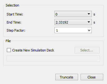
Truncate Results
You can remove results data (Time Steps) from your simulation either entirely, or 'thinned out' by removing every nth result.
-
Select .
-
In the Truncate File dialog box, specify the
Start Time and End Time to
define the Time Steps between which you want to remove data.
The Start Time and End time cannot be partial Time Steps, but simulations including partial Time Steps can be truncated.
-
Select a Step Factor from the dropdown list or
specify a new value.
This determines how often a Time Step in the range is removed. If the Step Factor is set to one, every Time Step will be retained. If it is set to greater than one, the data in the range will effectively be 'thinned out'. The greater the Step Factor, the more the data is removed.
By default, the selected data will be truncated from the current simulation deck.
-
Select the Create New EDEM Simulation Deck checkbox
to truncate to a new simulation deck.
The original deck is unaffected.