EDEM Analyst
EDEM Analyst is the post-processor used to analyze and visualize the results of your simulation.
- Configure and control the EDEM simulation engine
- Play back the simulation, graph results, save a still image, and create a video or export data
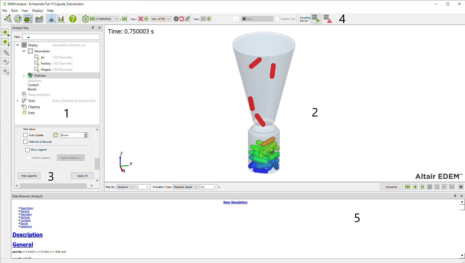
- The Analyst Tree
- The Viewer
- Section Details
- Analyst Toolbar and Menu Bar
- The Data Browser
The Analyst Tree
The Analyst Tree is displayed on the left side of the EDEM window and comprises five sections - Display, Setup Selections, Tools, Clipping, and Field. Right-click the Analyst Tree to expand/collapse all the corresponding subsections.
The Viewer
The Viewer displays 3D representations of your particles, Geometry, and fields (if applicable). The rotation, position, and zoom factor of the Viewer are controlled using the mouse. There are a number of animation controls displayed below the Viewer.
Section Details
The Section Details space contains all the information and configuration options for each section of the Analyst Tree. The options displayed within the Section Details correspond to the section or subsection being highlighted in the Analyst Tree.
The Tool Bar and Menu Bar
| Icon | Name | Description |
|---|---|---|
| Creator | Opens EDEM Creator | |
| Simulator | Opens EDEM Simulator | |
| Analyst | Opens EDEM Analyst | |
| Open | Opens an existing model | |
|
|
3D Viewer | Opens the 3D Viewer |
|
|
Create Graph | Opens the Graph creator |
| Help | Displays the online Help | |
| Jump to Start | Moves to the first Time Step in the simulation | |
|
|
Animate Backwards | Changes Time Steps backwards continuously |
|
|
Step Backwards | Moves a step backwards |
|
|
Stop Animation | Stops the animation |
|
|
Step Forwards | Moves a step backwards |
|
|
Animate Forwards | Changes Time Steps forwards continuously |
|
|
Jump to End | Moves to the last Time Step in the simulation |
|
|
Record Animation | Records the animation |
|
|
Save View | Saves the current view settings |
|
|
Delete View | Deletes the current view settings |
| Start Coupling Server | Starts the Coupling Server | |
| Coupling Server Disabled | Disables the Coupling Server | |
| Server Awaiting Connection | Indicates that the Coupling Server has started but not connected | |
| Server Connected | Indicates that the Coupling Server is connected | |
| Stop Server | Stops the Coupling Server | |
|
|
Add Text | Adds text to the Viewer |
|
|
Delete Text | Delete text from the Viewer |
|
|
Add Selection | Adds a selection to the analysis |
|
|
Manual Selection | Adds a manual selection to the analysis |
|
|
Grid Bin Group | Adds a Grid bin |
|
|
Geometry Bin | Adds a Geometry bin |
|
|
Add Sensor Selection | Adds a Sensor Selection |
|
|
Mass Flow Sensor | Adds a Mass Flow sensor |
|
|
Total Mass Sensor | Adds a Total Mass sensor |
|
|
Velocity Profile Sensor | Adds a Velocity Profile sensor |
|
|
Segregation Sensor | Adds a Segregation sensor |
|
|
Density Sensor | Adds a Density sensor |
|
|
Imported Geometry Bin | Adds an imported Geometry bin |
|
|
Copy Selection Group | Copies the Selection group |
|
|
Delete Selection Group | Deletes the Selection group |
| File Menu | |
|---|---|
| Open | Opens an existing model |
| Truncate File | Removes sections of data from your model |
| Export | |
| Simulation Deck | Allows you to export single, full, Time Steps from your simulation to create a copy as a new EDEMsimulation deck (you cannot export from partial save Time Steps). Exporting a deck allows it to be transferred to another location and run using identical simulation parameters. |
| Results Data | Allows you to export specific data for analysis |
| Continuum Data | Allows you to export force data on a specific Geometry in a text format suitable for Continuum analysis |
| HyperMesh Data | Allows you to export pressure and force data on a specific Geometry in a text format suitable for HyperMesh import |
| SimSolid Data | Allows you to export force data on a specific Geometry in a text format suitable for SimSolid import |
| ANSYS Workbench Data | Allows you to export pressure and force data on a specific Geometry in a text format suitable for ANSYS Workbench import |
| Data to STL | Allows exports of Geometries and particles to a CAD file |
| Breakage Particle Size Distribution | Allows export of the size distribution of particles produced when using the breakage model |
| Image | Allows you to save a copy of the image currently displayed in the Viewer |
| Print Image | Prints a copy of the image currently displayed in the Viewer |
| Run EDEMpy Script | |
| Runs an EDEMpy Analyst script by navigating to . You can select a previously generated EDEMpy script and the additional arguments used in the script can be passed to Python in the Arguments section. | |
| Import Config | Imports a config (*.dfg) file |
| Export Config | Exports a config (*.dfg) file |
| Creator | Starts EDEM Creator |
| Simulator | Starts EDEM Simulator |
| Analyst | Starts EDEM Analyst |
| Recent Files | Displays a list of recently opened files |
| Quit | Exits EDEM |
| View Menu | |
|---|---|
| Themes | Select Legacy (default) or Dark Theme for the EDEM interface |
| Toggle Display Command Line Output | Select to display command line output |
| Displays Menu | |
|---|---|
| Show 1 Display | Shows the EDEM window in a single display. |
| Show 2 Displays | Shows the EDEM window in two viewer displays to review different view-points of the model within each window |
| Show 3 Displays | Shows the EDEM window in three viewer displays to review different view-points of the model within each window |
| Show 4 Displays | Shows the EDEM window in four viewer displays to review different view-points of the model within each window |
| Split Display Horizontally | Splits the displays horizontally so that simulations may be simultaneously reviewed qualitatively and quantitatively on the same display |
| Split Display Vertically | Splits the displays vertically so that simulations may be reviewed both qualitatively and quantitatively on the same display |
| Help Menu | |
|---|---|
| Help | Displays information about the EDEM interface |
| About EDEM | Displays the current version of EDEM. The EDEM Version and Revision number are useful for EDEM Technical Support when discussing support cases. |
| About Altair Simulation Products | Displays the Copyright notices, Altair website, License Agreements, and Customer Support information. |
The Data Browser
The Data Browser is a
.html page that displays detailed information about your model.
The information displayed differs between the Creator, Simulator, and Analyst.
Right-click the Data Browser and select Save to save the
information in an .html file.
| Section | Description |
|---|---|
| Description | Available in the Project section of the Analyst Tree |
| General | Gravity Displays details of the gravity acting in your model as specified in the Globals pane |
| Materials Lists all the materials used in the model and their properties, as specified in the Materials Editor |
|
| Energy Displays the total energy in the model at the current time, which is the sum total of the kinetic energy, potential energy, and the energy in any contacts taking place |
|
| Dimensions Displays the number of dimensions in your domain |
|
| Geometry | Domain Lists the dimensions of the domain as specified in the Geometry pane |
| Sections Lists each section(model) and its properties |
|
| Geometry Totals Aggregates the details of the number of elements that make up each section of the Geometry |
|
| Particles | Particles Lists each particle type used in the model and their properties as specified in the Particles pane. The details of each surface within the particle are also listed. |
| Factories Lists the details of each factory used in the model and their properties as specified in the Factory pane. The total number of particles created by each factory is also listed. |
|
| Particle totals Lists the total number of particles in the model at the current time. Totals for each particle type are also listed. |
|
| Contacts | Interactions Lists the interaction types taking place in the model as specified in the Materials Editor. |
| Contacts Lists the total number of contacts in progress at the current time. The contacts are broken down into contact types. For example, the number of particle A - particle B contacts or particle B - surface A contacts. The total number of collisions that have taken place during the Time Step are also listed. |
|
| Bonds | Bond Totals
Lists the total number of bonds, total number of intact and broken bonds, and the number of bonds intact/broken between particle pairs |
| Selections | List all Selections
Displays links to pages with information on the selection and its associated queries, list of particles, and Geometry elements (if applicable) |