Attribute Definitions
The following tables provide detailed descriptions for Particle, Geometry, Contact, and Collision attributes.
Particle Attributes
| Attribute | Description |
|---|---|
| Acceleration | Indicates the current acceleration of the particle, calculated from the Total Force and Mass of the particle. |
| Angular Velocity | Indicates the speed at which an object rotates. |
| Aspect Ratio | Indicates the ratio of two sides of the particle bounding box. You can select Max/Mid or Max/Min dimensions from the Component dropdown list. |
| Charge | Indicates the charge which is an electrical property of particles (such as electrons and protons) which causes them to attract and repel each other. A material with an excess of electrons has a negative charge; and a material with an absence of electrons (or an excess of protons) has a positive charge. Materials with a balanced number of electrons and protons are called 'neutral'. Positive and negative charges attract each other. |
| Compressive Force | Indicates the sum of the surface normal force magnitudes. |
| Coordination Number | Indicates the number of contacts that a particle has with the
spheres of another particle at any given point in time. The
following image of a 3-sphere particle shape represents four
particles placed on top of each other. 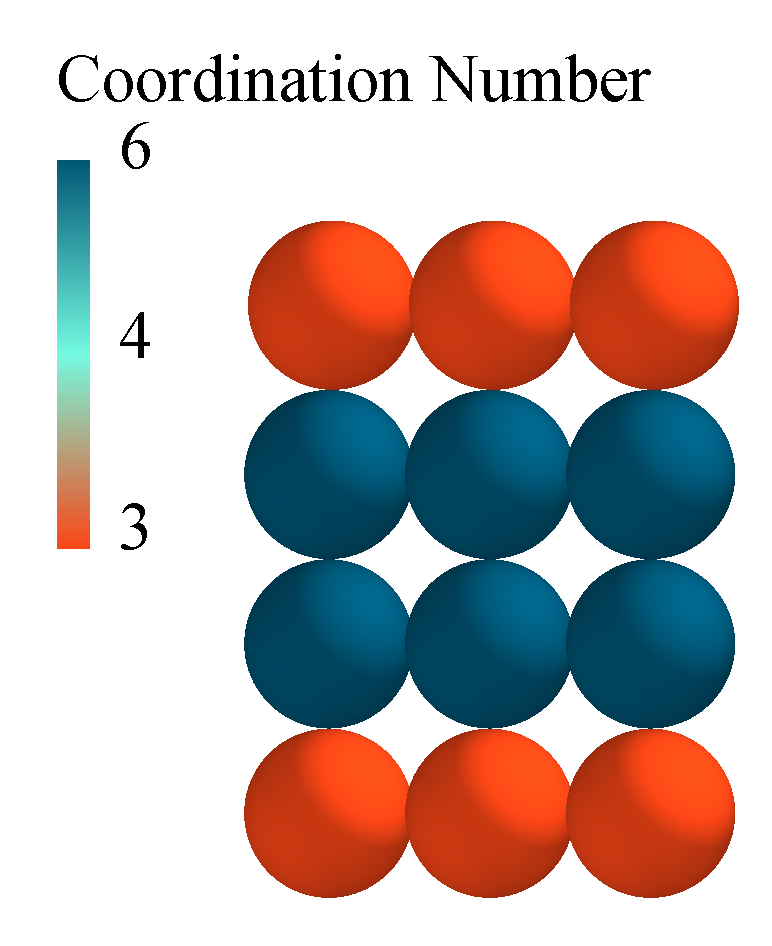 The base and top particles have a coordination number of 3, as each particle is in contact with 3 spheres of the middle particles. The middle two particles have a coordination number of 6 as they are in contact with 3 spheres of the particle above and 3 spheres of the particle. The Particle-Geometry contacts are not counted in the coordination number. |
| Diameter | Indicates the diameter of the particle (based on the largest X, Y, or Z component of the bounding box around the particle). |
| Distance | Indicates the distance between the center of a particle from a reference point or plane. |
| Electrostatic Force | Indicates the force of interaction between charged particles, measured in Newtons. The force is calculated using the screened Coulomb force equation. |
| ID | Indicates the unique ID of a Geometry element, particle surface, particle, and collision. |
| Frozen | Indicates that the particles which are frozen will be locked in position and excluded from the contact calculations. This is normally set by the Dynamic Domain capability. |
| Moment of Inertia | Indicates a measure of a particles resistance to a change of
momentum for a sphere defined as: |
| Kinetic Energy | Indicates the kinetic energy defined as: |
| Mass | Indicates the magnitude of the gravitational force on a
particle defined as: |
| Mass Scale | Indicates the parameter used to alter the particle mass and therefore, the density without altering the size of the particle. Typically used in wetting or drying simulations. |
| Number of Particles | Indicates the total number of particles in a simulation (or bin group) at that point in time. In a bin group, you can use the Total over time option. This will produce a cumulative particle count for any particles that pass through that bin group. The total over time option can only be used for bin groups with 1 bin. |
| Orientation | Indicates the alignment of a particle in relation to Cartesian space. It is represented as a 3X3 matrix that defines the rotation of the particle from its original orientation (as defined in Creator and assigned an identity matrix). |
| Position | Indicates the x, y, or z position of the center of the particle. |
| Potential Energy | Indicates the potential energy defined as: |
| Residence Time | Indicates the measure of how much time a particle has existed
in the simulation. “Residence time = Simulation Time - Particle
Creation Time”. You can set the simulation time by navigating to . This option will impact the Residence Time shown on the particles following the equation “Residence time = Simulation Time - Particle Creation Time” |
| Rigid Link | Indicates the parameter that locks the particle position and movement relative to a specified Geometry section. The value for Rigid link will be 0 when not active, and 1 when active. |
| Rotational Kinetic Energy | Indicates the energy defined as: |
| Scale | Indicates the parameter used to alter the size of the particle as typically set by the Size Distribution. |
| Shape Scale | Indicates the ability to allow anisotropic scaling of the particle along each axis of the bounding box. |
| Time | Indicates the real time it takes for an event to occur. |
| Torque | Indicates the tangential contact force * particle radius. |
| Total Energy | Indicates the sum of the kinetic energy, rotational kinetic energy, and potential energy of a particle. |
| Total Force | Indicates the resultant unbalanced forces on a particle or Geometry element in x, y, and z. |
| Velocity | The velocity of the particles is defined as the rate of change of displacement (in x, y and z) |
| Voidage | Indicates the percentage of space not taken up by particles.
Voidage can be obtained by creating a Grid Bin and Voidage
query. The Voidage property is defined as: |
| Volume | Indicates the volume of a particle after all scaling factors have been applied. |
Geometry Attributes
| Attribute | Description |
|---|---|
| Charge | Indicates the electrical property of Geometries (such as electrons and protons). A material with an excess of electrons has a negative charge; a material with an absence of electrons (or an excess of protons) has a positive charge. Materials with a balanced number of electrons and protons are called 'neutral'. Positive and negative charges cause an attractive force to be applied between the elements (Particle-Geometry). |
| Compressive force | Indicates the sum of the surface normal forces on the Geometry. |
| Distance | Indicates the distance from the center of a Geometry node from a reference point or plane. |
| Electrostatic force | Indicates the force of interaction between charged elements, measured in Newtons. The force is calculated using the screened Coulomb force equation. |
| ID | Indicates the unique ID of a Geometry element, particle surface, particle, and collision. |
| Node 1, 2, 3 | Indicates the position (x, y, and z) of the Geometry nodes. |
| Number of geometry elements | Indicates the sum of the Geometry elements. Geometries are split into triangular elements. |
| Position | Indicates the X, Y, or Z position of the center of the Geometry element. |
| Torque | Indicates the tangential contact force * distance, where
distance is the distance from the center of mass to the contact
point.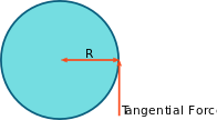 The torque is calculated from the individual torque and moment about each individual Geometry element which is then converted to the torque on the whole Geometry about the center of mass. The torque can be plotted or exported along the x, y, and z axis. |
| Total Force | Indicates the resultant unbalanced forces on a particle or geometry element in x, y , and z. |
| Velocity | Indicates the rate of change of displacement of the individual Geometry nodes. |
Contact Attributes
| Attribute | Description |
|---|---|
| Contact vector 1,2 | Indicates the vector connecting the contact point to the
center of the particle when two particles collide.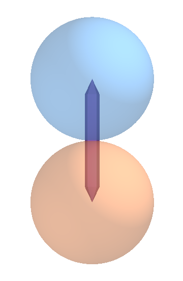 |
| Distance | Indicates the distance from the point of contact to a user-defined point or plane. |
| Normal force | Indicates the force that is created when two bodies are in direct contact with one another. It always acts perpendicular to the body that applies the force. The force depends on the contact model used, and will be a spring force with a damping component. The reported force on particles includes damping forces, and the reported force on Geometries is the undamped force. |
| Normal overlap | Indicates the normal deformation of a particle. The normal
overlap N between two particles i and j at positions
pi and pj with radii ri and
rj is defined as: |
| Number of contacts | Indicates the number of contacts or impacts occurring between elements at data write-out points. In other words, the contact is in progress when the write-out takes place. The contact has an associated force, position and so on - these are discrete values. If two elements stay in contact with each other for some time. For example, over four write-out points, four contacts will be stored and each of these may have a different force, position and so on |
| Position | Indicates the central point between two elements at the point in time when a contact starts. |
| Tangential force | Indicates the force from the tangential overlap.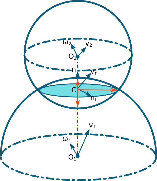 |
| Tangential overlap | Indicates the tangential displacement of the contact point up to the point at which the contact ends or the particle begins to roll or slip. The tangential overlap represents the tangential deformation of a particle. |
| Time | Indicates the real time it takes for an event to occur. |
Collision Attributes
| Attribute | Description |
|---|---|
| Average normal force | Indicates the average normal force over the duration of a single collision. |
| Average tangential force | Indicates the average tangential force over the duration of a single collision. |
| Distance | Indicates the distance from the collision position to a user defined point or plane. |
| Duration | Indicates the total time that the two elements involved in a collision are in contact. |
| End time | Indicates the time at which the collision ends. |
| ID | Indicates a unique number which can be used to track the unique collision and the elements involved. |
| ID Element n | Indicates a unique number for each element in a collision. |
| Maximum normal force | Indicates the maximum normal force experienced during a single collision. |
| Maximum tangential force | Indicates the maximum tangential force experienced during a collision. |
| Normal energy loss | Indicates the energy lost during a collision due to the normal overlap. |
| Number of collisions | Indicates the number of completed collisions. Only completed collisions are counted, and collisions in progress (contacts) are not counted. |
| Position | Indicates the central point between two elements at the point in time when a collision starts. The collision position is written out on completion of the collision. |
| Relative velocity | Indicates the relative velocity of two elements in a
collision is Va - Vb. Note: This value is calculated from the
contact points and not the particle centers. |
| Indicates the value calculated from the contact points and not the particle centers. | |
| Relative velocity normal | Indicates the relative normal velocity of two elements in a collision is Vna - Vnb. |
| Relative velocity tangential | Indicates the relative tangential velocity of two elements in a collision is Vta - Vtb. |
| Start time | Indicates the point in time when the first contact of a collision occurs. |
| Tangential energy loss | Indicates the energy lost during a collision due to the tangential overlap. |
| Time | Indicates the real time it takes for an event to occur. |
| Total energy loss | Indicates the sum of the normal and tangential energy loss. |
| Velocity of element A/B | Indicates the velocity magnitude of an element involved in a collision. Element A will have the lowest ID number and element B will have the highest. |