Node Path
![]()
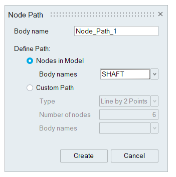
This tool is used to create user defined paths and can visualize the contour, vector and tensor on those defined paths.
Once the paths are created, contours or vectors are updated automatically when the results components are changed in the results panel.
- Nodes in Model
- Custom Path
- This option will create a path by connecting the selected nodes in the existing
model.
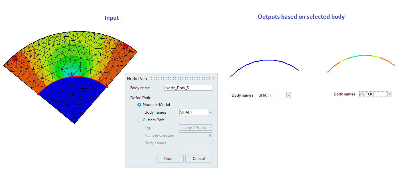
If the shared node is selected, the associated bodies will be listed under "Body names". Depending on the selected body, the contour will be updated for the node paths.
-
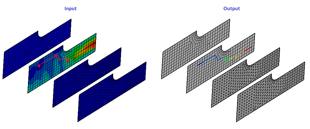
Example:
Contour display in the defined Node Path
Shared Node Input Case
Custom Path
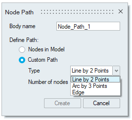 We can define custom path by using any one of these options:
- Line by 2 Points
- Arc by 3 Points
- Edge
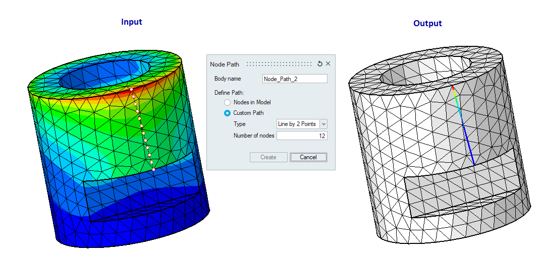
Line by 2 Points
Pick any two nodes or vertices and specify the number of nodes that needs to be created on the defined line.
Example:
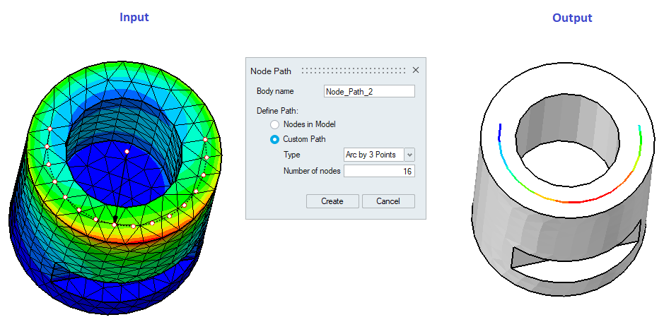
Arc by 3 Points
Pick any three nodes or vertices and specify the number of nodes that needs to be created in the defined arc.
Example
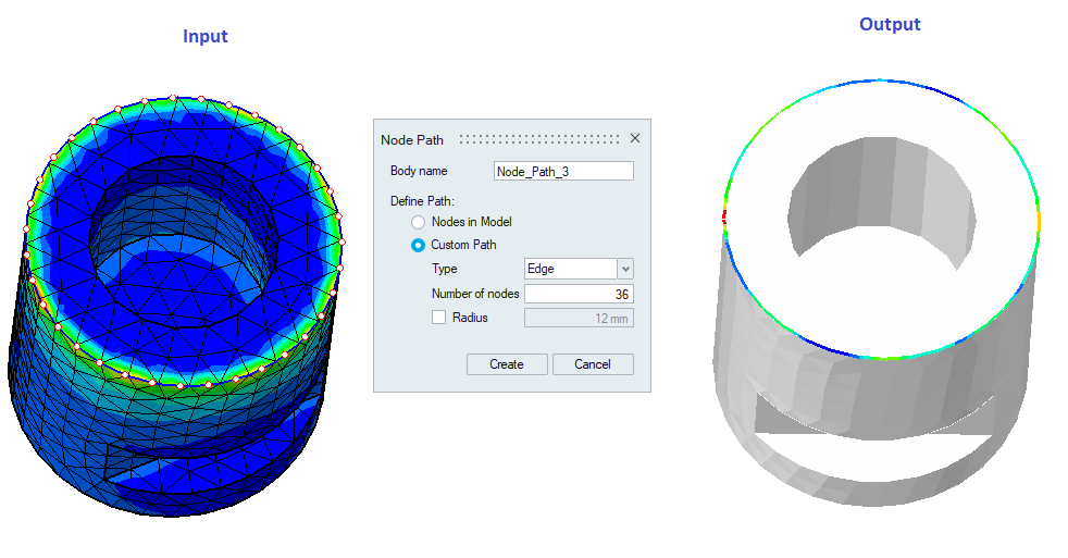
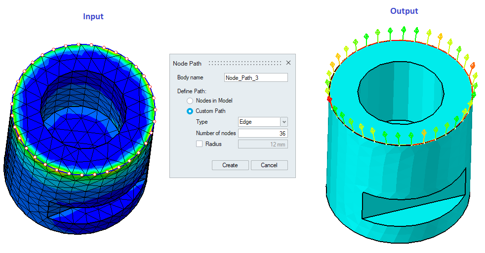
Edge
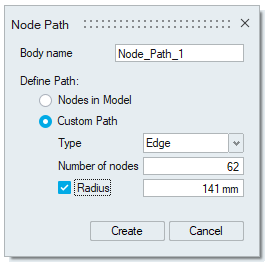
Pick topological edge for path definition and number of nodes will be updated automatically based on the picked edge.
Radius option will be shown only if the picked edge is an arc edge.
Example
Contour display in the Path
Vector display in the path
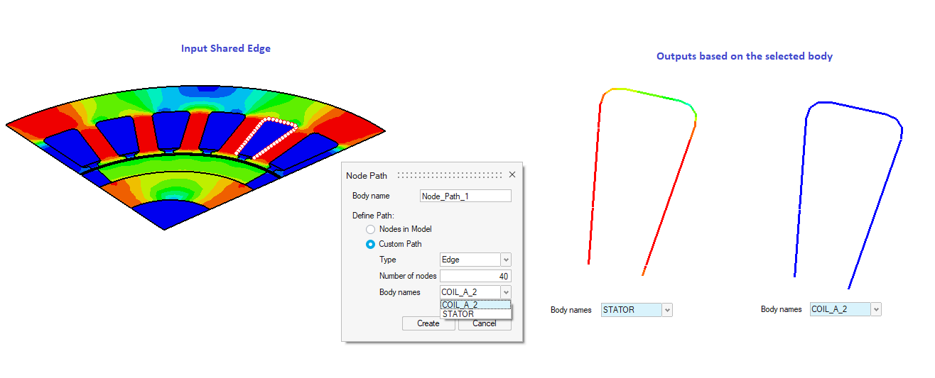
 Note: In the case of Line by 2 Points and Arc by 3 Points, we can pick points arbitrarily on the model if the selection filter is turned OFF.
If the shared edge is picked, then the bodies associated with the selected edge will be listed in the body names option. Based on the selected body, contour is updated for the created node paths.
We have options to display the vectors along the result component, normal and tangential direction. Supported only for Flux Results. Refer Results Panel for details.