Imposed Current Coil - 3D Solutions
Introduction for 3D Magnetostatic solution
Introduction for 3D Transient Magnetic and 3D AC Magnetic solutions
Dialog Box
| MS3D and MT3D | MAC3D | ||
|---|---|---|---|
| Internal Terminals | External Terminals | Internal Terminals | External Terminals |
 |
 |
 |
 |
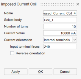
- Select body: Select the body to define as a coil
- Number of turns: Enter the number of turns of the coil
-
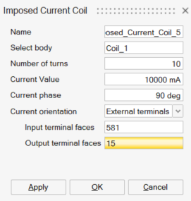
Current Value: Enter the current value
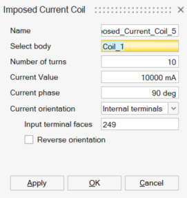
Note: For the 3D AC Magnetic solution, enter the rms value -
Current phase for the 3D AC Magnetic solution only, enter the current phase value
- Conductor connection: is used if
symmetry or periodicity entities are existing. This input allows to define
the symmetric or periodic coils as in Series or in
Parallel or with Number of conductors
in parallel. That means that if a current
"I" is flowing into the represented coil, then
each symmetric or periodic coil will have:
- in series: I
- in parallel: I divided by the total number of
coils in the complete deviceNote: for example, if the device has one symmetry, the current on the represented coil and in the symmetric coil will be I/2. If the device has a periodicity with a total of 6 portions, the current on each portion coil will be I/6.
- with Number of conductors in parallel:
Table 1. Possible associations between periodical conductors in the example. Symmetries and Periodicites: number of conductors in series or in parallel Equivalent circuit association between conductors All in series or Number of symmetrical and periodical conductors in parallel = 1 
Number of symmetrical and periodical conductors in parallel = 2 
Number of symmetrical and periodical conductors in parallel = 3 
All in parallel or Number of symmetrical and periodical conductors in parallel = 6 
- Current orientation: allows to
define the current orientation into the coil body. There are two
possibilities:
- Internal Terminals: defines the current orientation in a closed coil (not cut by a symmetry nor periodicity). To define this orientation, Input terminal faces corresponding to coil body's internal face(s) have to be selected. As soon as this selection is done, a preview of the current direction is displayed through an arrow. It is possible to change the direction through Reverse orientation checkbox.
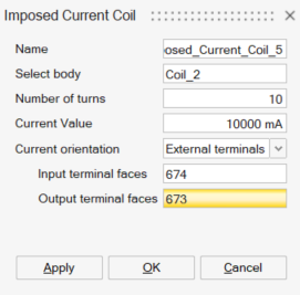
- External terminals: defines the current orientation in a coil which is not closed (cut by a symmetry or periodicity). To define this orientation, Input terminal faces and Output terminal faces have to be selected.
Steps
- Prerequisite: The bodies to define as Imposed Current Coils must be volume meshed.
-
Click on the Imposed Current Coil button in Analysis ribbon:

→ The corresponding dialog box is opened.
→ If there are already created Imposed Current Coil entities, the associated previews become visible on the graphic. It allows an easy definition if the device contains several coils.
- Select the body corresponding to a coil
- Enter the Number of turns
→ You can see that now only the selected body is shown on the graphic
- Enter the Current Value
- Select the Conductor
connection
There are three possibilities: Series or Parallel or Number of conductors in parallel. (See Conductor connection for more explanations)
- Select the Current
orientationThere are two possibilities: External terminals or Internal terminals
- Internal terminals is selected when the
coil is closed and is fully represented (not cut by symmetry or
periodicity).
-
Select face(s) in Input terminal faces corresponding to coil body's internal face(s).
→ As soon as this selection is done, only body's internal face(s) are visible and a preview of the current direction is displayed through arrow(s) starting from the Input terminal faces
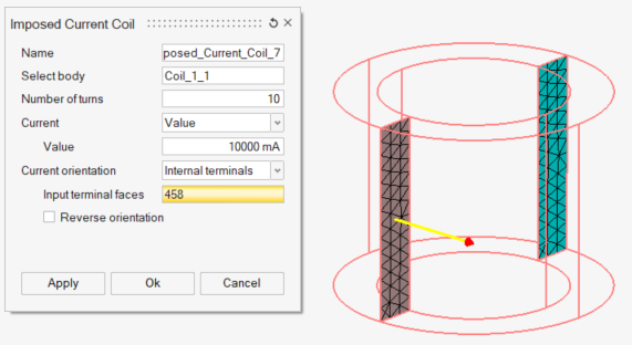
-
It is possible to reverse the direction through Reverse orientation checkbox and see the preview updated.
Note: To create internal face(s) in the coil body, please follow the workflow using Break command on CAD bodies detailed in Break -
- External terminals is selected when the
coil is not closed (cut by symmetry or periodicity)
- Select the Input terminal
faces
It is the face(s) through which the current enters
→ A preview of the current direction is displayed through arrow(s) on the Input terminal faces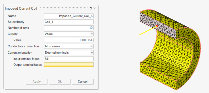
- Select the Output terminal
faces
It is the face(s) through which the current exits
→ A preview of the current direction is displayed through arrow(s) on the Output terminal faces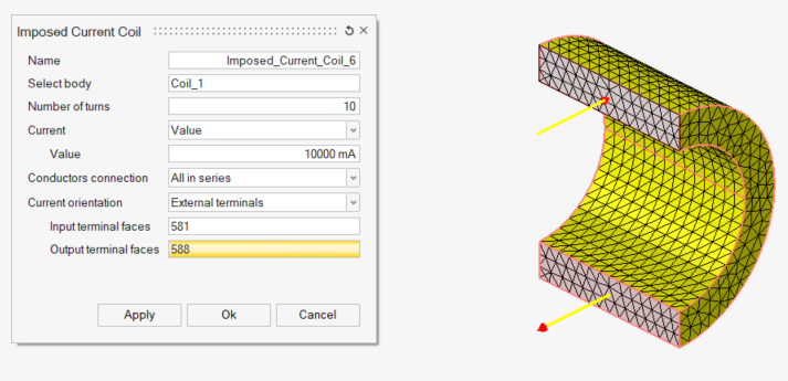
- Select the Input terminal
faces
- Internal terminals is selected when the
coil is closed and is fully represented (not cut by symmetry or
periodicity).
-
If there are already created Imposed Current Coils, it is possible to check again the defined orientation in comparison with the existing ones by clicking on any field which is not Input/Output faces field.
- Click on the OK or
Apply buttonNote: Apply button is trully advised in case of several Imposed Current Coil entities creation.
Display Imposed Current Coil preview
Adding to the preview visualisation during Imposed Current Coil creation and edition, the command Display Preview allows to display Imposed Current Coil previews at any time.
For that, right-click on the Imposed Current Coil entities and click on Display Preview command.
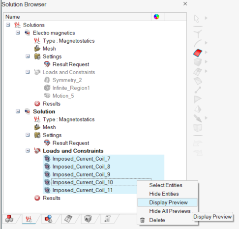
→ All the selected Imposed Current Coil entities previews become visible on the
graphic: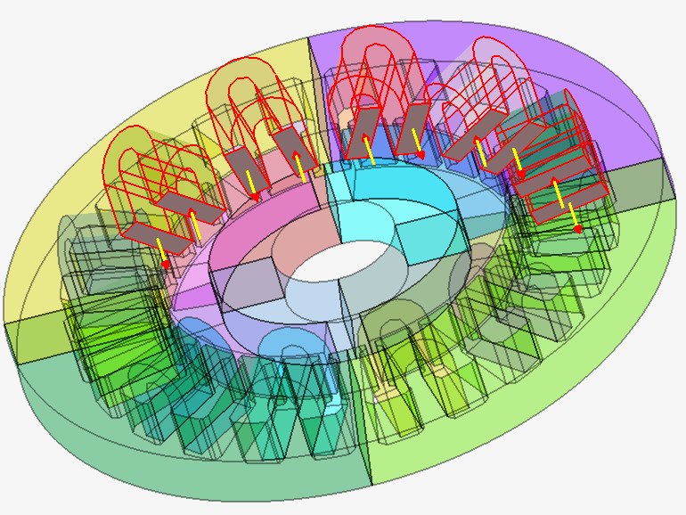
The command Hide All Previews in the same contextual menu allows to hide the preview and reset the graphical view.
Advices
For Internal terminals current orientation, To create internal face(s) in the coil body, please follow the workflow using Break command on CAD bodies detailed in Break