Cuts
Cut is a common feature for several electromagnetic solutions:
| Cuts | MS | MSIM | MT | MAC | ES | PE | SC |
| 2D | - | - | - | ||||
| 3D |
The documentation is common for all these EM solutions.
Introduction
Notion of connected space

The Connected space and the Simply connected space are correctly managed.
The Non-connected space (two objects) for a group of bodies is forbidden.
The Multiply-connected space is the configuration of a group of bodies have hole(s): cut(s) are necessary (except for specific configurations detailed later).
The number of cut(s) to create is equal to the number of hole(s). For example: if 2 holes exist as in this image, two cuts must be created.
Concept of cut

Cut types for 3D Magnetostatic solution
- Magnetic Circuit Cut: The cut(s) are done on the magnetic circuit.
Cut types for 3D Transient Magnetic and 3D AC Magnetic solutions
- Magnetic Circuit Cut: The cut(s) are done on the magnetic circuit.
- Electric Loop Cut: The cut(s) are done on the electric loop also called solid conductor. The solid conductor can be either a group of bodies assigned to the Passive solid conductor load and constraint or to the Solid conductor circuit component
Configurations for Magnetic Circuit Cut creation

Configurations for Electric Loop Cut creation

With symmetry or periodicity

If a group of bodies having hole(s) is cut by a periodicity plane, then cuts may be necessary. This configuration is not managed yet.
Automatic Cuts creation for 3D Magnetostatic solution
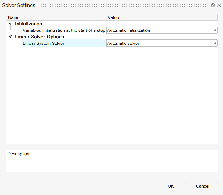
By default, the automatic magnetic circuit cuts creation is enabled. User does not need then to create any cut manually.
The option is available in the Solver Settings:
If the option is enabled, when solving the solution, if one or more holes are detected on the magnetic circuit, then a message is displayed to confirm the execution of the automatic cuts creation algorithm:
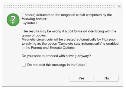
- If Yes is selected, the Flux automatic cuts creation algorithm is executed before the solving.
- If No is selected, the solving is cancelled.
It is possible then to disable the automatic cuts creation in the Solver Settings and create manually all the magnetic circuit cuts (see the section Steps for Magnetic Circuit Cut creation below).
It is also possible to keep the automatic cuts creation in the Solver Settings and create some of the cuts manually. The automatic cuts creation algorithm will complete by creating the missing cuts.
Automatic Cuts creation for 3D Transient Magnetic and 3D AC Magnetic solutions
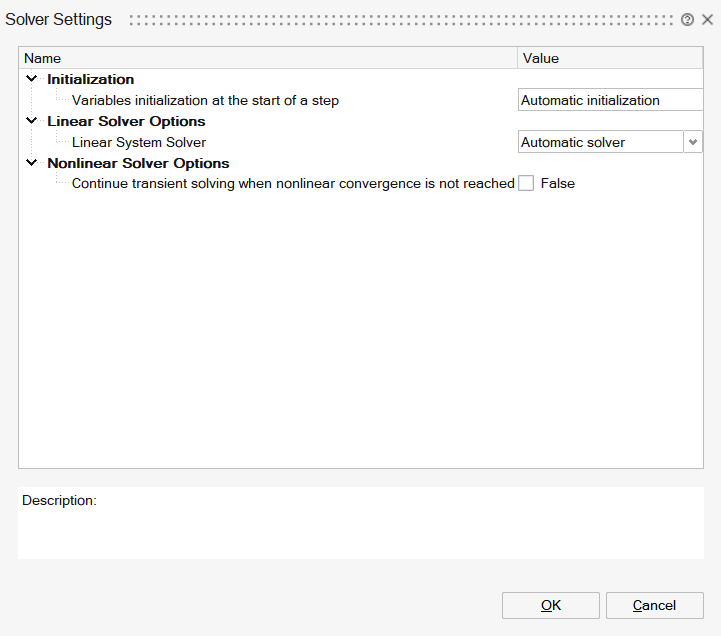
By default, the automatic cuts creation is enabled. User does not need then to create any cut manually.
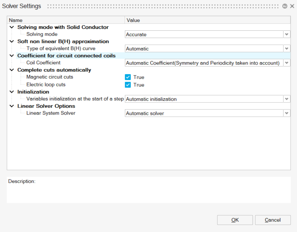
The options for both magnetic circuit cuts and electric loop cuts are available in the Solver Settings:
| 3D Transient Magnetic | 3D AC Magnetic |
|---|---|
 |
 |
If the options are enabled, when solving the solution, if one or more holes are detected, then a message is displayed to confirm the execution of the automatic cuts creation algorithm:
- If Yes is selected, the Flux automatic cuts creation algorithm is executed before the solving.
- If No is selected, the solving is cancelled.
It is possible then to disable the automatic cuts creation in the Solver Settings and create manually all the cuts (see the sections Steps for Magnetic Circuit Cut creation and Steps for Electric Loop Cut creation below).
It is also possible to keep the automatic cuts creation in the Solver Settings and create some of the cuts manually. The automatic cuts creation algorithm will complete by creating the missing cuts.
Steps for Magnetic Circuit Cut creation
- On the solution Loads ribbon, Click on the buttons:
 → A message appears. There are three possible messages:
- Information message saying that the cuts are not needed if there is no hole
- Warning message if there is a magnetic circuit group of bodies with holes. The Magnetic Circuit Cuts creation are mandatory only if a coil with a non-zero current supply forms an interlacing with the group of bodies.
- Blocking error message if there is connectivity issue. This may happen if the number of created cuts loads is higher than the number of holes.
Note: The check is also done when running the solving - If holes are detected by the check, Cuts are required (except for some
cases)
If the check detects holes on the magnetic circuit group of bodies and if a coil with a non-zero current supply forms an interlacing with the group of bodies, Magnetic Circuit Cuts loads must be created. The number of Magnetic Circuit Cuts must be equal to the number of holes. To create the cuts, the internal faces of the group of bodies must be selected. Only connected faces can be selected in one cut load.
The button to create Magnetic Circuit Cut is:
On the example below, one hole exists on the magnetic circuit. So one Magnetic Circuit Cut must be created by selecting one internal face:
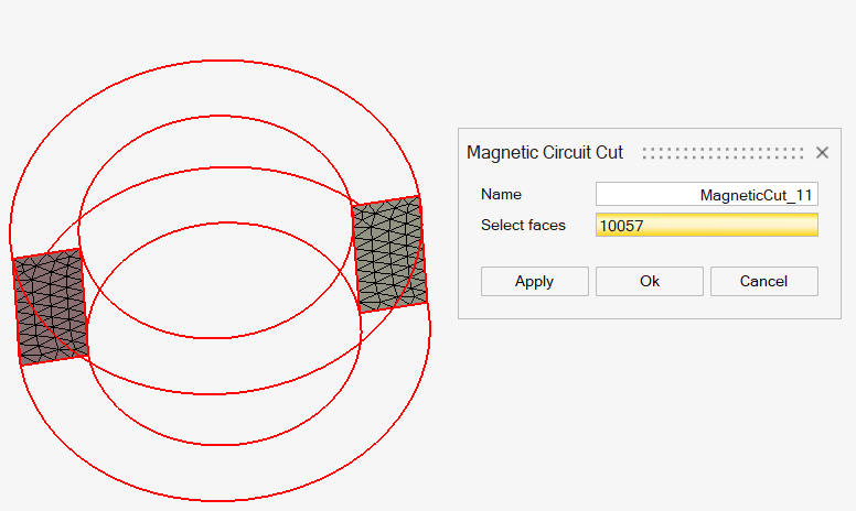
The load is created in the loads and constraints of the Solution Browser: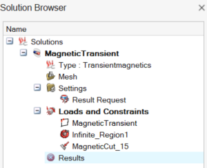
Steps for Electric Loop Cut creation
- On the solution Loads ribbon, Click on the buttons: → A message appears. There are three possible messages:
- Information message saying that the cuts are not needed if there is no hole
- Blocking error message if there is an electric loop (solid conductor) group of bodies with holes. The Electric Loop Cuts creation is mandatory.
- Blocking error message if there is connectivity issue. This may happen if the number of created cuts loads is higher than the number of holes.
Note: The check is also done when running the solving - If holes are detected by the check, Cuts are required (except for some
cases)
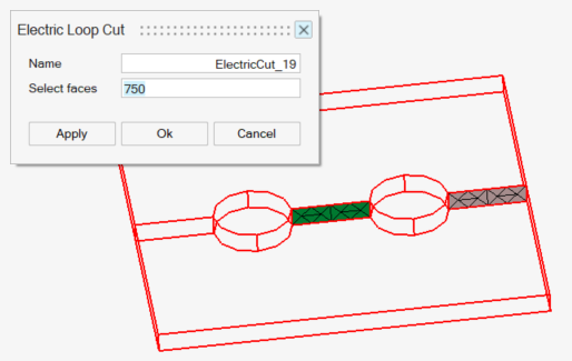
If the check detects holes on the electric loop (solid conductor) group of bodies, Electric Loop Cuts loads must be created. The number of Electric Loop Cuts must be equal to the number of holes. To create the cuts, the internal faces of the group of bodies must be selected. Only connected faces can be selected in one cut load.
The button to create Magnetic Circuit Cut is: On the example below, two holes exists on the electric loop. So two Electric Loop Cuts must be created by selecting one internal face for each one:
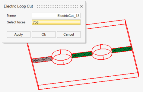
 The load is created in the loads and constraints of the Solution Browser:
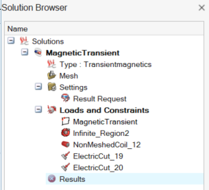
Limitations
The cut is a mathematical trick which is not obvious to understand. That is why ideally the cuts should be created automatically. The automatic cuts creation will be available in the future.
In the current release, the cuts check is not taking into account the usecase of periodic devices with holes located on the periodicity plane. Those holes will not be detected by the check.