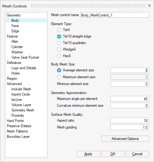
Mesh Controls
![]()
Introduction
The Mesh Controls allows you to choose the mesh element order, to set the mesh element size, … on particular areas requiring a specific mesh.
Dialog Box
In the case of 3D Magnetostatic, 3D Transient Magnetic, and 3D AC Magnetic solutions:
- The first 3 in the Geometry category: Body, Face and Edge. And in many cases, using only Body is sufficient.
- The Symmetry Mesh mesh control in case of periodic device like a part of motors. It allows to copy the mesh of period starting faces to the period ending faces.
- The Proximity mesh control to refine the mesh on the very closed bodies, on the area within the defined distance.
- The Element TypeAs part of the MS3D Workflow, MT3D Workflow, and MAC3D Workflow, it is recommended to use:
- Tet4 corresponding to 1st order tetrahedral mesh elements
or- Tet10 quadratic (particularly advised for curvilinear shapes to get more precise results) corresponding to 2nd order tetrahedral mesh elements which are necessary if there are solid conductors and if the Solver Settings Solving mode with Solid Conductor is set to Accurate (it is the default value). But please note that 2nd order mesh can lead to huge solving time increase in 3D.
Important: It is mandatory to have the same mesh order on all the bodies of the solution (Mesh Controls, Surface Mesh and Tet Mesh): all should be either of 1st order mesh only or all should be of 2nd order mesh only. - The Mesh Size
For example by entering the Average element size.
Steps to assign Body mesh control
- Click on the Mesh Controls button in
Mesh ribbon:

- For example, in our contactor project, we adjust the mesh on the
bodies:
Select in the left part, in the Geometry category, Body.
- We choose a 1st order mesh with tetrahedral elements:
In Element type, check Tet4.
- For the 2 bodies corresponding to the 2 coils:
As the coils are very thin, it is necessary to mesh them with a very fine mesh.
To help you determine the size of the mesh element to set, you can use the Measure / Distance button located above the graphic window, 2nd button in the ribbon:

Click successively on the 2 end points of the coil thickness and it displays the distance value, here: 0.5 mm.
So we set a mesh element size of 0.5 mm on these 2 coil bodies (there will be one layer of elements in the thickness):
- In Body Mesh Size, in the Average
element size field, enter 0.5
mm.

- Select the 2 bodies corresponding to the 2 coils:
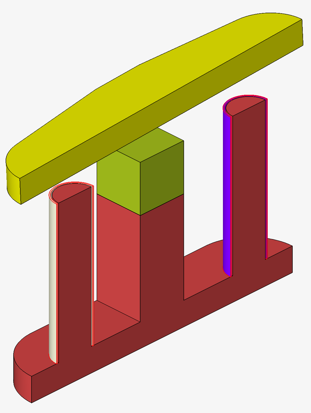
The outlines of the 2 coil bodies are displayed in red.
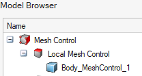
- Click on the OK button.
To the left of the graphic window, in the Model Browser, in the 4th tab Mesh Control, the Body_MeshControl_1 entity is created:
- In Body Mesh Size, in the Average
element size field, enter 0.5
mm.
Advices
- Create and assign Mesh Controls on the bodies requiring a specific mesh (finer, ...) then mesh all the bodies via Surface Mesh and then Tet Mesh (it will respect mesh control information).
- Have the same mesh order on all the bodies of the solution is mandatory:
1st order mesh only or 2nd order mesh only.For example, for Mesh Controls:
- 1st order mesh with tetrahedral elements: Tet4, for faster meshing and solving
- 2nd order mesh with tetrahedral elements: Tet10 quadratic (particularly advised for curvilinear shapes to get more precise results), necessary if there are solid conductors and if the Solver Settings Solving mode with Solid Conductor is set to Accurate (it is the default value).
Limitations
Currently it is not possible to have quadrangular 2nd order surface elements on the solution bodies external faces. In fact, the infinite box cannot be created.