Create Axial Flux Machine
![]()
Introduction
This tool is used for the modeling of axial flux machines, including both the geometry creation and motor meshing.
The “Create AFM” tool described in this document can help to build an AFM model in SimLab for the following electromagnetic or multi-physics analysis.
Principle of Axial Flux Machine
Axial flux motors (also known as "pancake motor") have a different magnetic flux path from radial flux motors. With this geometry of electric motor construction, the air gap of an axial flux motor is planar, and the direction of the air gap magnetic field is parallel to the direction of the motor axis.
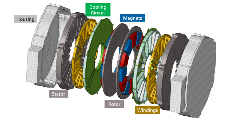
Axial flux motors have many EV design advantages over the radial flux motors. The core technical advantage of the axial flux motor is that the rotating rotor is structurally located on the side of the stator (rather than inside the stator), and then the rotor can have a larger. This means that under the premise of providing the same permanent magnet material and copper wire material, higher torque output can be obtained
Dialog Box
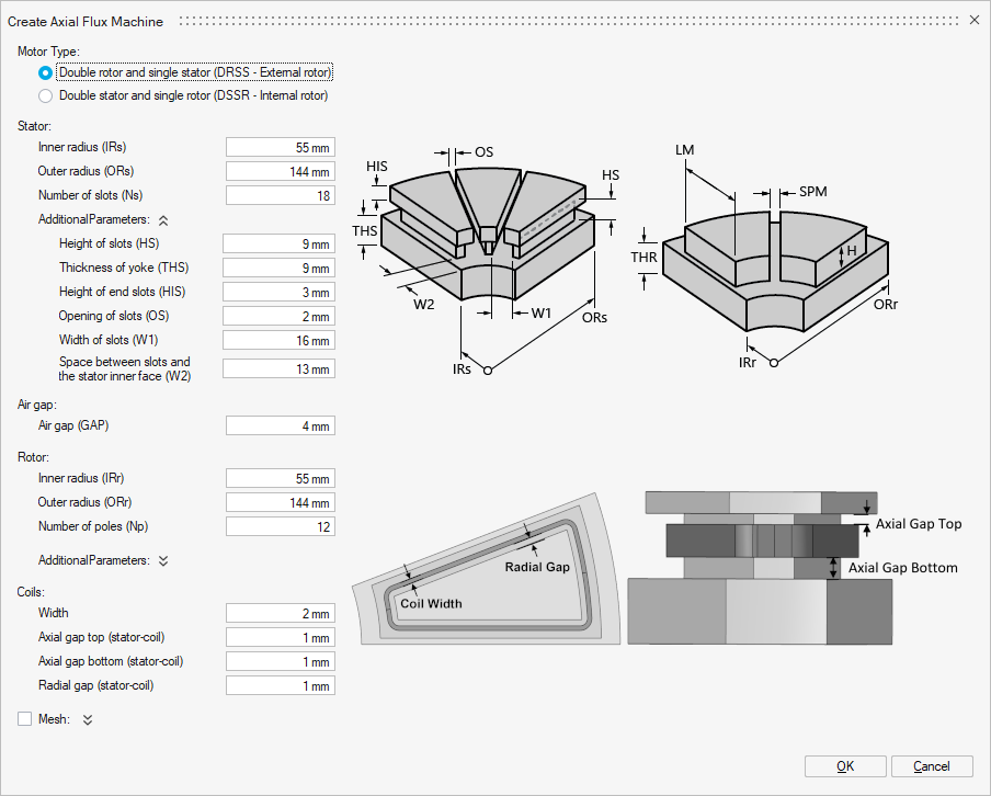
The dialog box contains several field and parameters to configure:
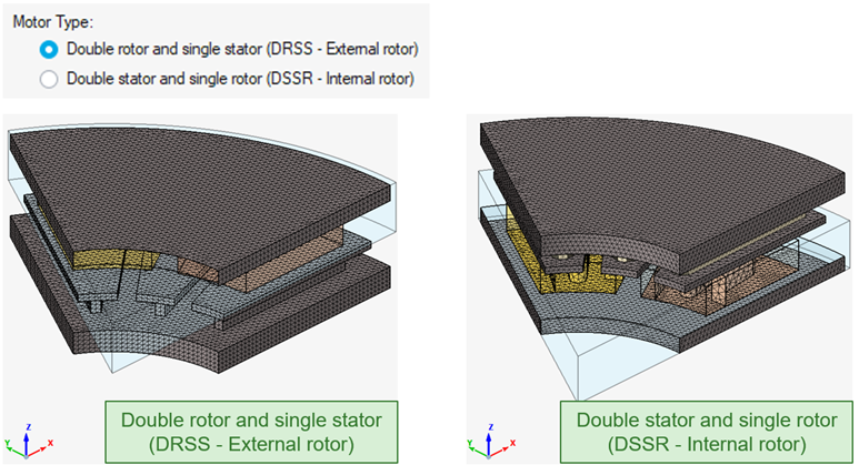
- Motor type
Two different motor configurations, the DRSS (external rotor) and the DSSR (internal rotor) are available, as shown below:
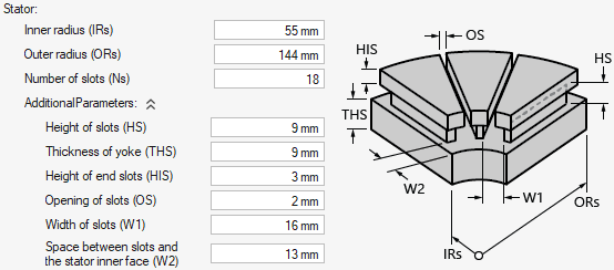
- Stator modeling
There are a total of nine geometric parameters (some detailed parameters are hidden in the Additional Parameters drop-down menu) to control the modeling of the stator, as shown below:
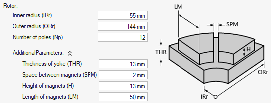
- Rotor modeling
Similar to the stator modeling, there are a total of seven geometric parameters (some detailed parameters are hidden in the Additional Parameters drop-down menu) to control the modeling of the rotor, as shown below:
- Air gap modeling
The air gap between the stator and the rotor is controlled by the parameter GAP
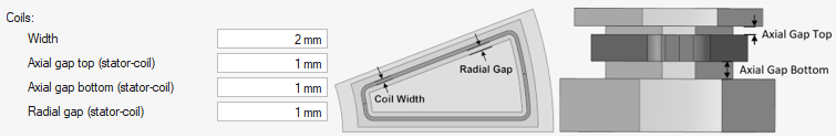
- Coils modeling
Establishing geometric models of windings can help to use mesh coil in the following electromagnetic analysis to enhance the result accuracy. As shown below, the coil size is controlled by the parameter WIDTH, and the position of the coil is controlled by other parameters.
- Motor Meshing
By default, the motor meshing is not activated. In this case, after running the Create AFM tool, only the geometric model of the axial flux machine will be established without meshing.
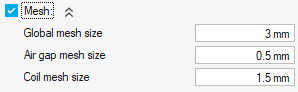
Once the meshing is activated, three mesh size parameters can be used to control the motor meshing:- Global mesh size is used for the stator / rotor / magnet regions
- Air gap mesh size (fine mesh) is used for the air gap region
- Coil mesh sized is used for the coil region
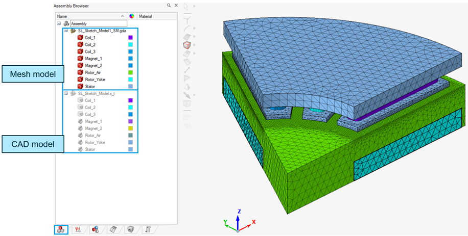
Running "Create AFM"
When all parameters are set, click on OK to generate the motor model.
→ The generated motor model (both the mesh model and the CAD model) can be found in the Assembly Browser