Create 3D Motor
![]()
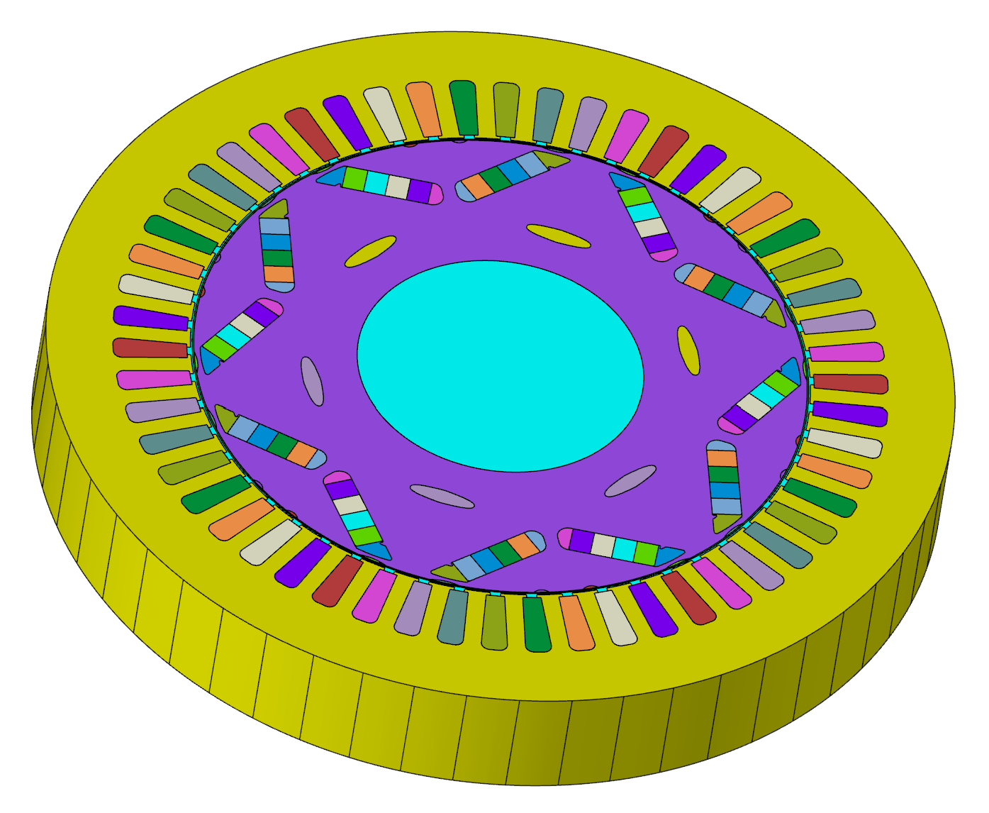
Introduction
This tool converts a 2D motor model into a 3D model, with options for non-skewed, step-skewed, and continuously skewed configurations, and also allows for the creation of an entire motor model.
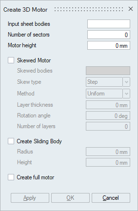
- Input sheet bodies
Select all the 2D CAD bodies for extrusion.
- Number of sectors
Describes the number of parts required to assemble the entire motor.
- Motor height
Defines the distance for extruding the motor.
- Skewed Motor
It is an option dedicated to creating rotating electric machines with skewing. For more details, refer to the Skewed Motor Option.
- Skewed bodies
Select all the bodies that require skewing.
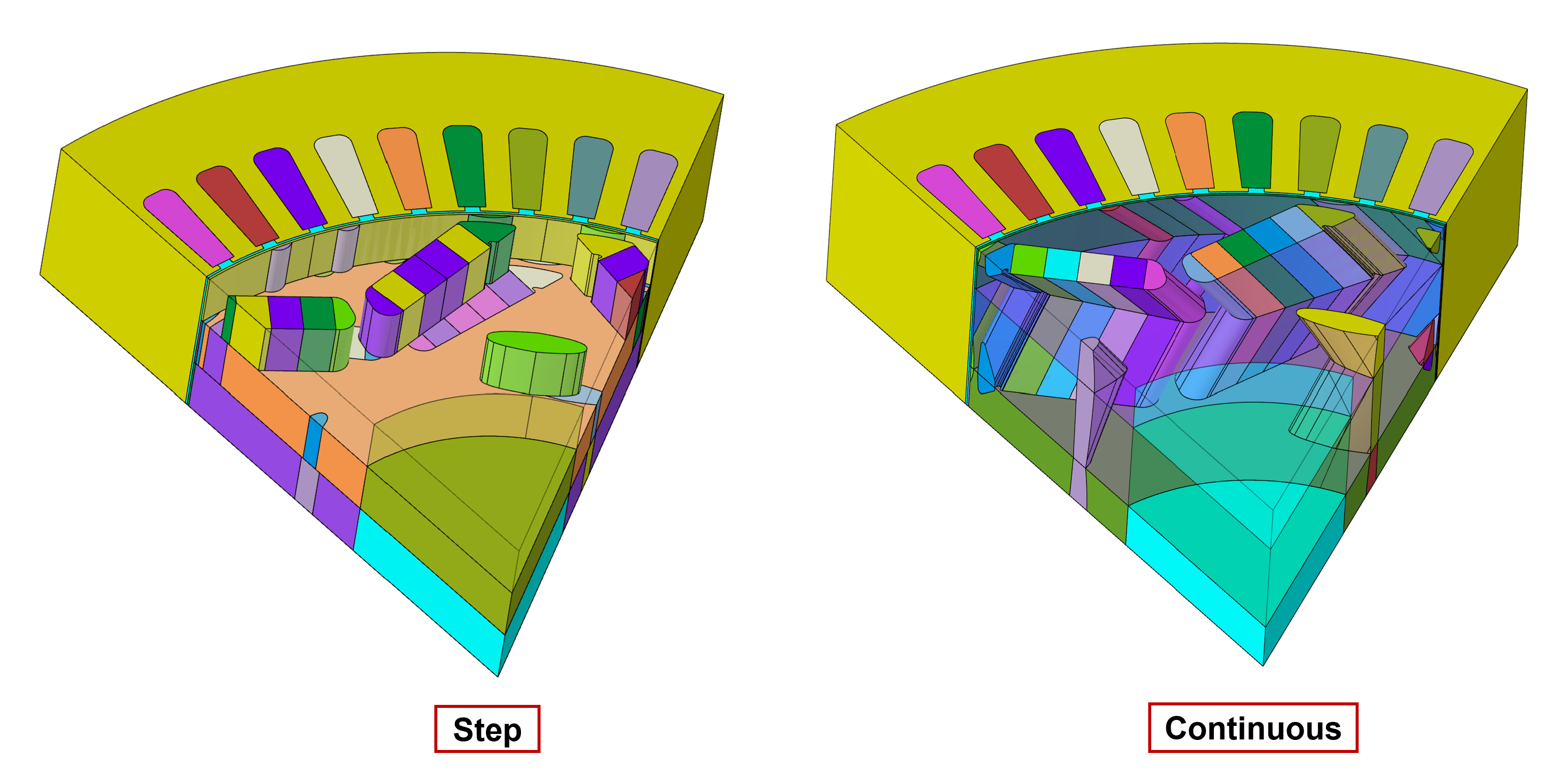
- Skew type
Step and continuous skew involve adjusting the angular position of components along the machine's axial direction. Step skew makes these adjustments in discrete increments, whereas continuous skew changes the position gradually. The figure illustrates these adjustments.
- Method
There are two approaches for defining skewed parameters: Uniform and Layer-by-Layer. The uniform method applies a consistent thickness to all layers, while the layer-by-layer method allows for varying thicknesses in each layer.
- Layer thickness / Axial length
For the uniform method, it defines the extrude distance for each layer. In the case of the layer-by-layer method, the user will specify the thickness and its respective skew angle using a table format.
- Rotation angle
Specifies the angular position for rotating the skewed components.
- Number of layers
Determines the total number of skewed layers to be applied.
- Skewed bodies
- Create Sliding Body
Generates a sliding body at the rotor top, as illustrated in the figure.
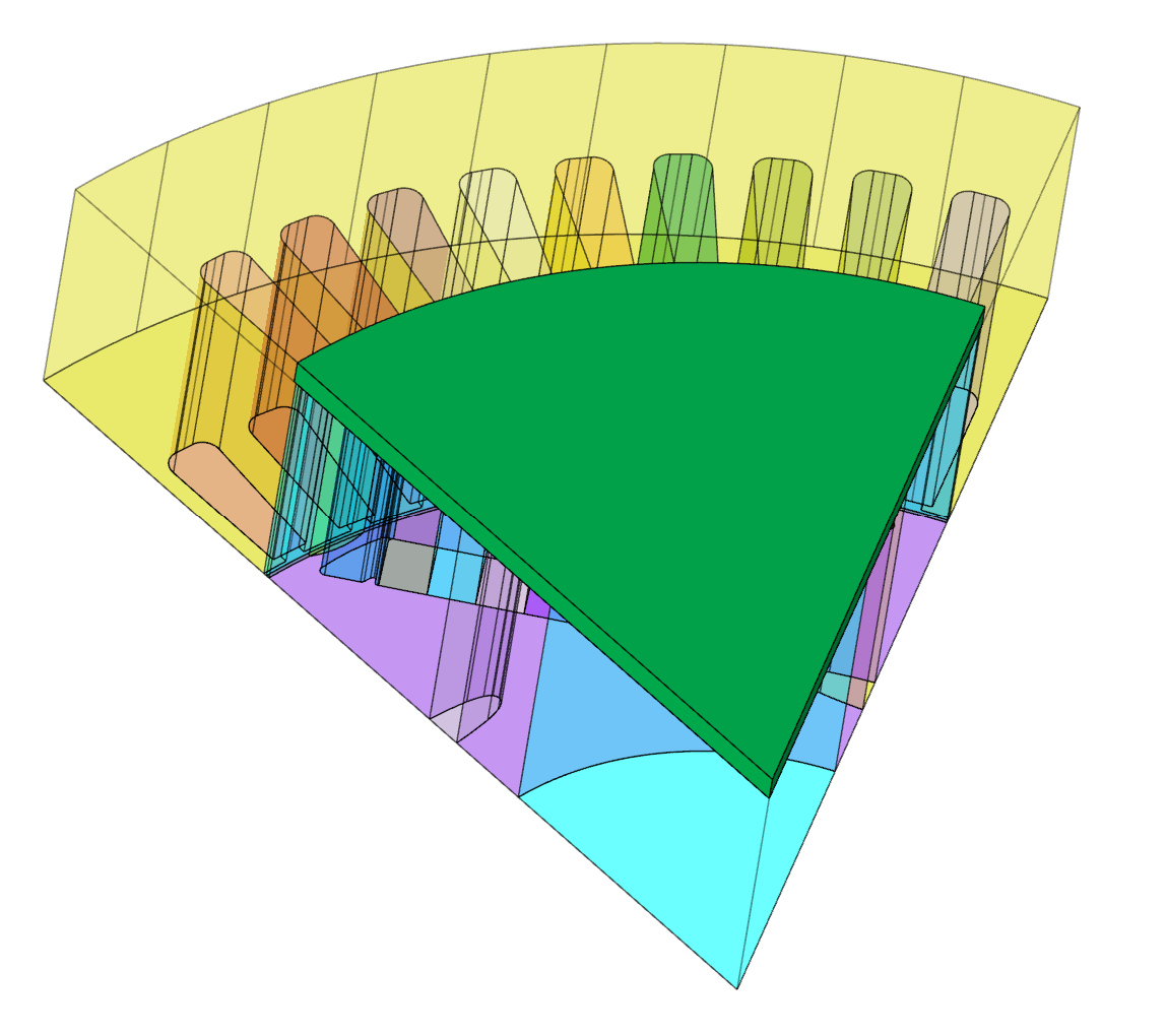
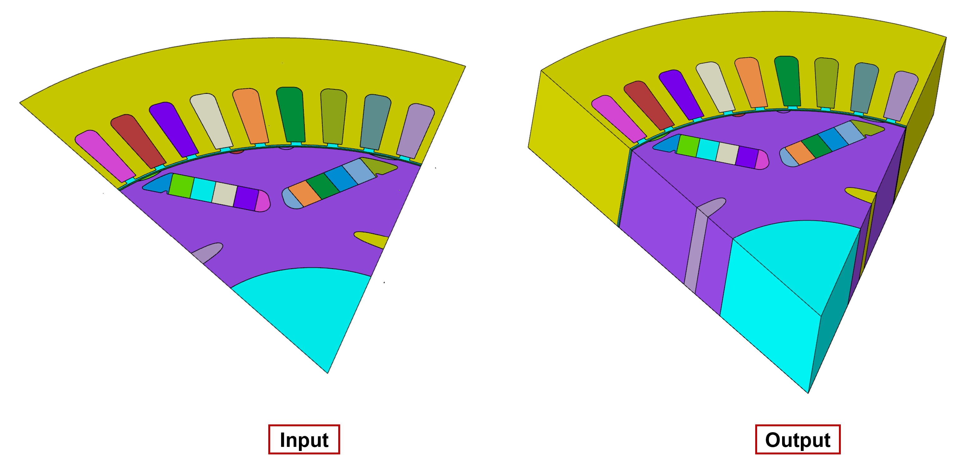
- Create full motor
It enables the creation of the complete motor from the provided periodic model, as shown in the figure.