Manual RBE
![]()
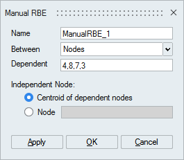
This tool is used to define Rigid Body Elements between faces / edges / nodes.
Description
- When RBE is created between faces / edges, SimLab will identify node pairs and create node to node RBE.
- Between nodes option can be used to create node to node RBE / node to nodes
RBE (Spider RBE).
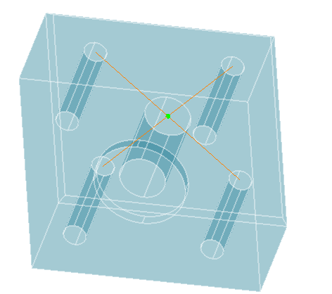
- Using centroid of dependent nodes option, center node will be calculated based on dependent node and highlighted in green color.
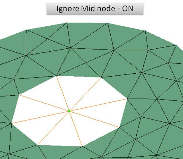
- Ignore mid nodes option can be used, if RBE should be
created only with corner nodes of the elements.
Ignore mid nodes 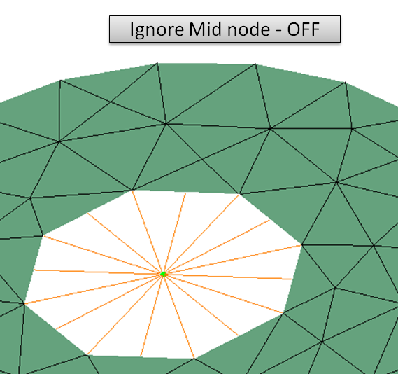
Example
Dependent and Independent Input Nodes
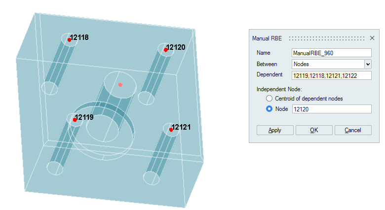
Output RBE Body
Cards supported for various solvers
RBE2
| Solver | Property(Element Type) | Supported Cards |
|---|---|---|
| Nastran | - | RBE2 |
| Abaqus | CONN3D2 | *CONNECTOR SECTION(with element type CONN3D2) |
| *KINEMATIC COUPLING | *KINEMATIC COUPLING | |
| *COUPLING,*KINEMATIC | *COUPLING,*KINEMATIC | |
| BEAM MPC | *MPC,BEAM | |
| EQUATION | *EQUATION | |
| Permas | - | $MPC RIGID |
| Ansys | - | CERIG |
RBE3
| Solver | Property(Element Type) | Supported Cards |
|---|---|---|
| Nastran | - | RBE3 |
| Abaqus | DCOUP3D | *DISTRIBUTING COUPLING(with element type DCOUP3D) |
| *COUPLING,*DISTRIBUTING | *COUPLING,*DISTRIBUTING | |
| *COUPLING,*DISTRIBUTING,Linear | *COUPLING,*DISTRIBUTING,WEIGHTING METHOD=LINEAR | |
| *COUPLING,*DISTRIBUTING,Quadratic | *COUPLING,*DISTRIBUTING,WEIGHTING METHOD=QUADRATIC | |
| *COUPLING,*DISTRIBUTING,Cubic | *COUPLING,*DISTRIBUTING,WEIGHTING METHOD=CUBIC | |
| Permas | - | $MPC WLSCON |
| Ansys | - | RBE3 |