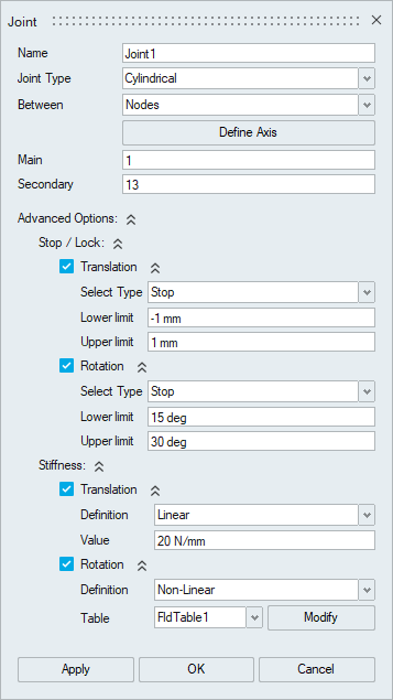
Joint
![]()
Description
Joint tool is used to connect selected parts/entities together while allowing movement at the joint location.
- Hinge
- Translator
- Cylindrical
- Ball
Hinge Joint:
Hinge joint is the type of joint allowing only one rotational motion along the axis of rotation.
Axis of rotation needs to be specified for nodal input using the “Define Axis” option.
Translator Joint:
Translator joint is the type of joint allowing only one translational motion along the axis of translation.
![]()
Axis of translation needs to be specified by using the “Define Axis” option.
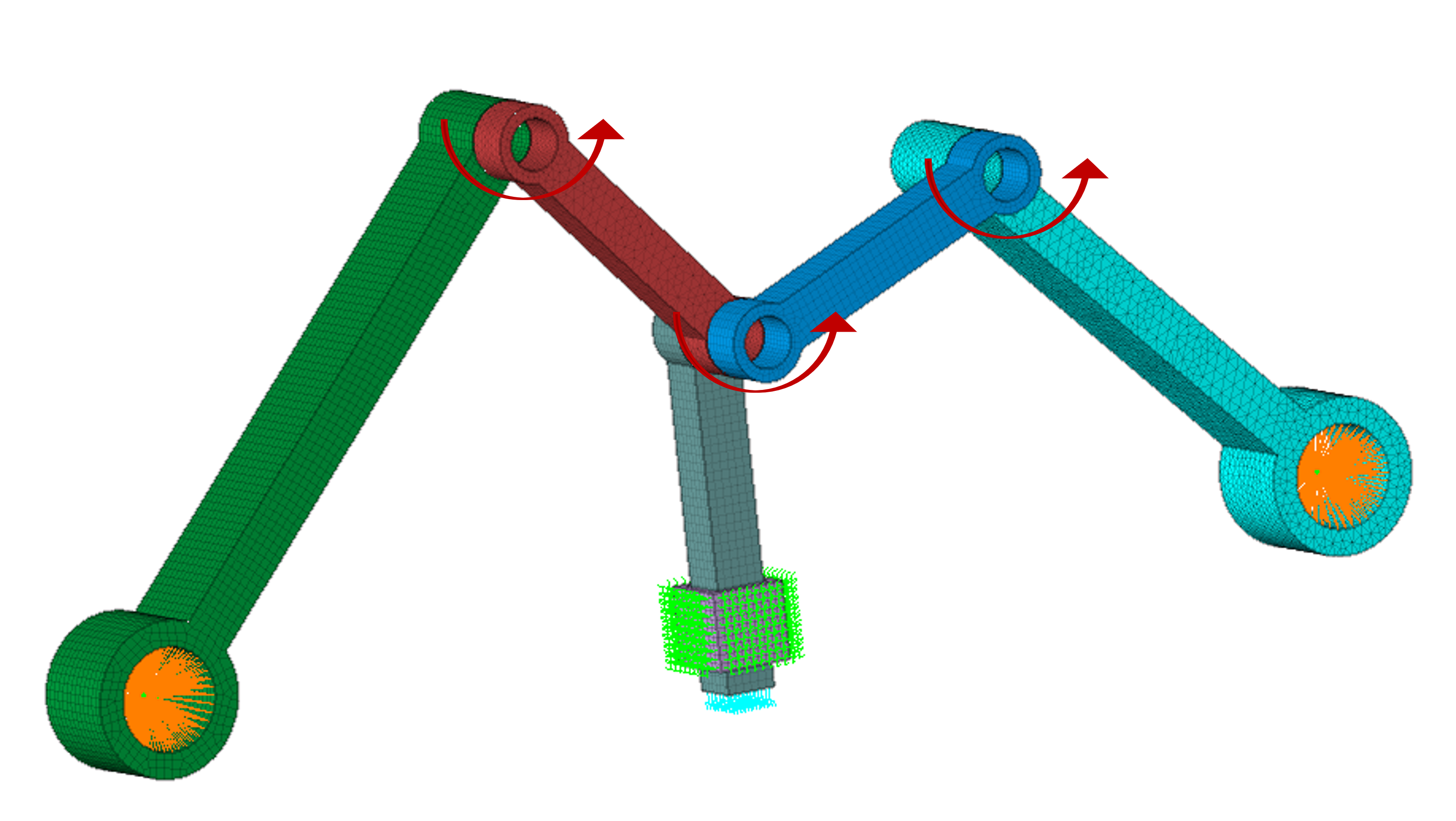
Cylindrical Joint:
Cylindrical joint is the type of joint allowing one translational and one rotational motion along the axis.
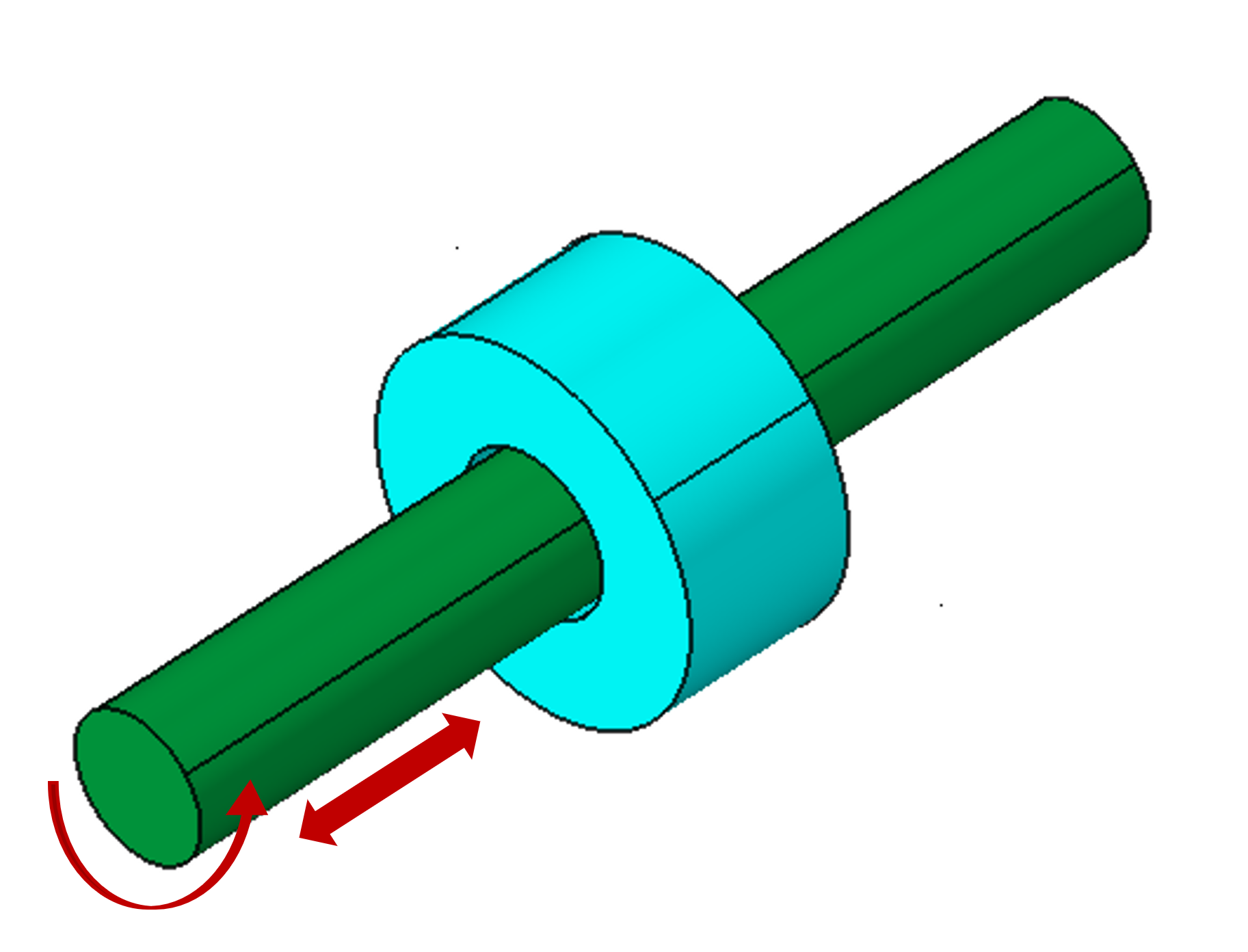
Axis of translation and rotation needs to be specified for nodal input by using the “Define Axis” option.
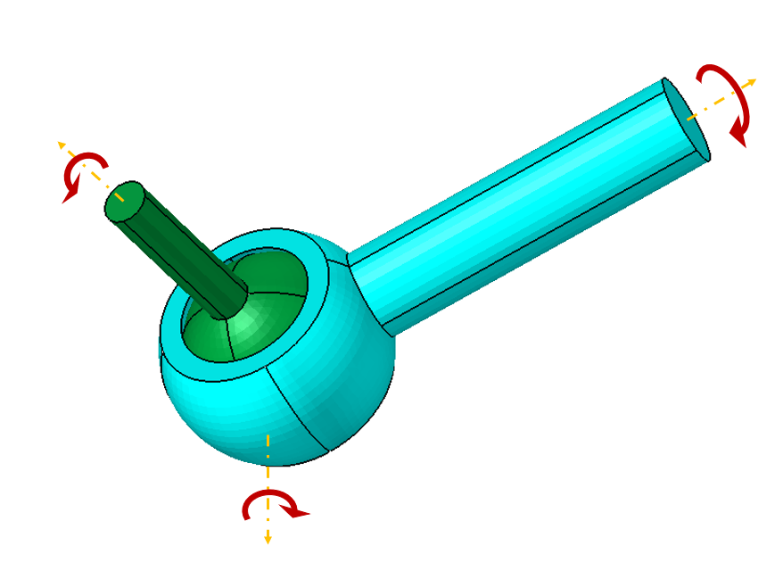
Ball Joint
Ball joint is the type of joint allowing only the rotational motion along all three axes.
- Bodies
- Faces
- Nodes
Body input:
- SimLab finds the face pairs between the selected bodies based on the type of joint.
- For hinge and cylindrical joint, SimLab find the cylindrical face pairs.
- For translator joint, SimLab find both cylindrical and planar face pairs.
- For ball joint, body input is not supported.
- RBE’s created separately for the main and secondary face pairs.
- Joint element will be created by connecting the centre node of the created RBE’s.
- Tolerance is used to find the face pairs from the selected bodies automatically.
- RBE’s created separately for the main and secondary face pairs.
- Joint element will be created by connecting the centre node of the created RBE’s.
- Joint element will be created between the two selected nodes.
Advanced Options:
- Stop
- Lock
- Stiffness
- Linear
- Non-Linear
- Rigid
Stop:
The relative displacement of the grid points associated with the joint is constrained within the lower limit and upper limit along the specified degree of freedom (DOF).
Lock:
The relative displacement of the grid points associated with the joint is constrained to move only within lower limit and upper limit along the specified degree of freedom (DOF) and when the value reaches either lower limit or upper limit, then the joint motion is locked, and further relative motion is not allowed.
- It is used to define the stiffness value for the joint element. User can define the Linear or Non-Linear stiffness.
- Also, user can define the joint as rigid.
- It is used to define the load (Force or Moment) on the Joint.
- It is used to define the enforced motion (Displacement or Angular Displacement) on the Joint.
Cards supported for various solvers
| Solver | Supported Cards |
|---|---|
| OptiStruct | JOINTG, PJOINTG, LOADJG, MOTNJG, JOINTD, JOINTF |
| Abaqus | *CONNECTOR SECTION, *KINEMATIC COUPLING, *CONNECTOR BEHAVIOR, *CONNECTOR ELASTICITY, *CONNECTOR LOCK, *CONNECTOR STOP |