The Bonding Pad dialog contains the following sections: Figure 1.
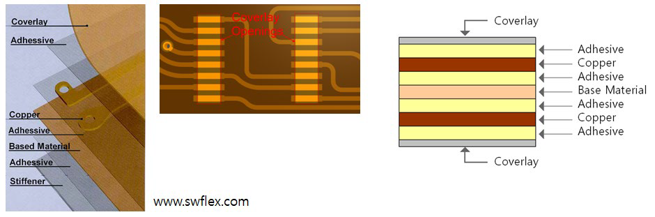
Coverlay Layer Definition: Define Coverlay layer for top and bottom.
Top/Bottom: Select Coverlay top and bottom layers from layer
list.
FPC Component Definition: Define FPC components.
Component Group Selection: Select FPC components from component
list.
Component Area Definition: Select FPC components’ area boundary.
Users can choose one of component ‘s area boundary among measure
(measured Min/Max rectangle area), COC (Component Overlap Check)
area, silk, pad and silk pad (silk and pad) region.
Checking
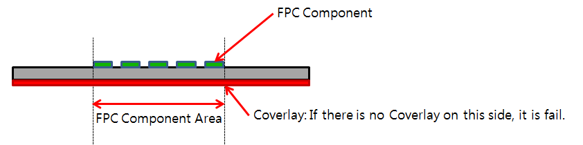
Coverlay Existence at Reverse Side of FPC Component: Check Coverlay
data existence on reverse side of FPC component. If there is no
Coverlay at reverse side of FPC components, PollEx DFM defines it as
fail. Figure 2.
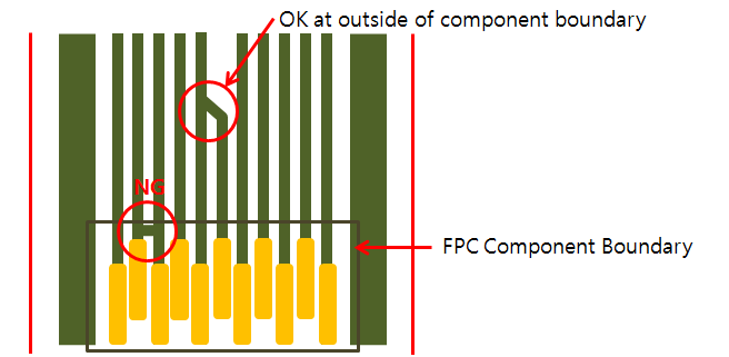
Pin to Pin Direct Connection Checking: Check whether FPC component’s
pins are connected within component area boundary. Figure 3.
Minimum Dummy Pad Count: Check the number of dummy pads. If the
calculated dummy pads’ counting number in FPC component is smaller
than given value, it is fail.
Finding Dummy Pad using Pin Name Filtering: To find dummy
pads with name in FPC component, use the string input
tool.
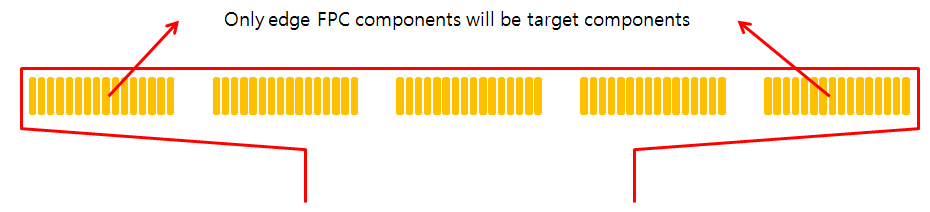
Check Dummy Pad Count for Edge FPC Component Only: Checking
this option, FPC target components will be edge FPC
components only. Figure 4.
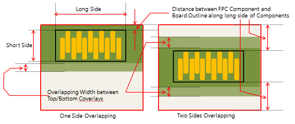
Check Overlapping Width between Top and Bottom Coverlays: Check the
overlapping distance between top and bottom coverlays. If measured
overlapped distance is smaller than given value, it is fail.
Distance between FPC Components and Board Outline along long
side of Component: To decide checking sides set the distance
between FPC component and board outline. After checking the
distance from long side of component to board outline, check
for the much distance long side than given value. If two
side distances are much longer than given value, check two
sides. Figure 5.