Introduction to Vehicle Modeling in MotionView
Tutorial Level: Beginner This tutorial will help you become familiar with the MotionView's Vehicle tools extension, an essential tool set for vehicle modeling.
- Invoke MotionView
- Load the Vehicle Tools Extension
- Configure a MotionView Session
- Browse Vehicle Tools Libraries
- Create a Full Vehicle Model
- Modify the Vehicle Model
- Add an Event
- Run a Simulation and Review the Results
Invoke MotionView
In this step, you will learn how to invoke a new MotionView session.
-
In Windows, click Start Menu
 > Altair <version> >
  MotionView
<version> OR use the Altair ConnectMe app (if installed).
Once invoked, the launcher window appears as shown in the image below.
MotionView
<version> OR use the Altair ConnectMe app (if installed).
Once invoked, the launcher window appears as shown in the image below.Figure 1. Launcher Window 
- Select MotionView and create a new session.
-
In Linux, invoke
~hw_install/altair/scripts/mviewin an open terminal (where~hw_installis the location of the installation).
Load Vehicle Tools Extension
In this step, you will learn how to load the Vehicle Tools extension in MotionView.
-
From the menu bar, click .
Figure 2. Select Extensions 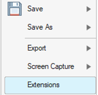
-
In the Extensions manager, use the slider to load the Vehicle
Tools extension.
Figure 3. Extensions Manager 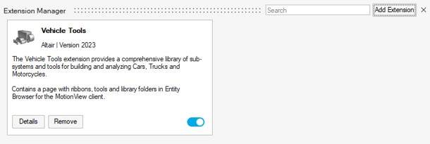
Note: Once loaded, the Vehicle Tools Ribbon is appended to the menu bar. From now on, the extension comes pre-loaded with MotionView, therefore it is not necessary to load it every time it is launched.
Configure a MotionView Session
In this step, you will learn how to enable the Entity Browser and Entity Editor windows.
- From the menu bar, click View and select Entity Browser and Entity Editor.
-
The Entity Browser and Entity
Editor are displayed on the right side of the MotionView page.
-
The Entity Browser contains the Vehicle Tools
library:
- Vehicle Tools Components are displayed
below. These components can be included in any MotionView model.
Figure 4. Vehicle Components Available in the Entity Browser 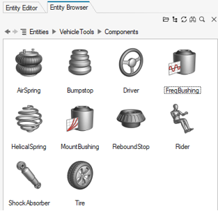
- Vehicle Tools Events allow you to add
vehicle analysis Cars,
Trucks,
Motorcycles and Tires test
rigs. The figure below shows the vehicle events
available for full vehicle models from the Car &
Small Truck library.
Figure 5. Car & Truck Events 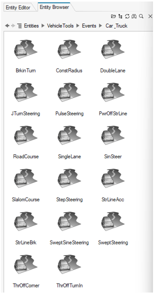
- Vehicle Tools Examples are available to
demonstrate the main MotionView
tools. As shown in the figure below, a collection of different
full vehicles models can be added in MotionView.
Figure 6. Vehicle Model Examples 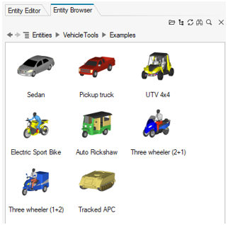
- Vehicle Tools Components are displayed
below. These components can be included in any MotionView model.
-
The Entity Browser contains the Vehicle Tools
library:
Browse Vehicle Tools Libraries
In this step, you will learn how to access the vehicle libraries.
-
From the Vehicle Tools ribbon, click on the
Libraries tool
 to invoke the Set wizard library dialog.
Figure 7. Setting Wizard Library of Preference 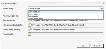
-
Click on the Wizard library drop-down menu to reveal the
following options:
- Car/Small truck
- Heavy truck
- Two-wheeler
- User/Custom library
- Car/Small truck
- The following models are eligible for creation through the Car/Small
truck library:
- Front end of vehicle
Figure 8. 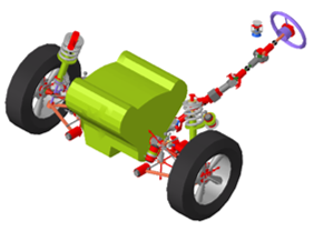
- Rear end of vehicle
Figure 9. 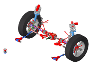
- Full vehicle with driver
Figure 10. 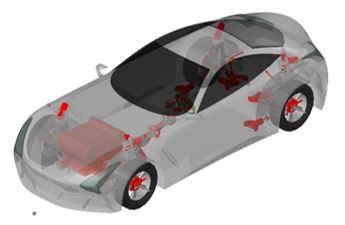
- Test rig
Figure 11. 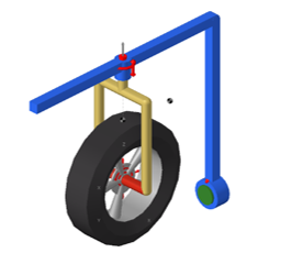
- Powertrain model
Figure 12. 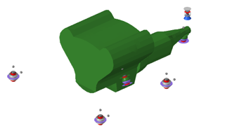
- Front end of vehicle
- Heavy truck
- The following models are eligible for creation through the Heavy
truck library:
- Front end of truck
Figure 13. 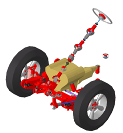
- Rear end of truck
Figure 14. 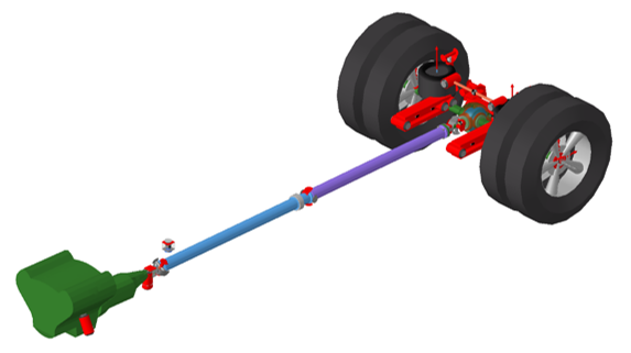
- Full truck with driver
Figure 15. 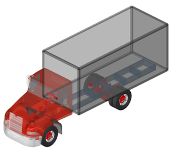
- Front end of truck
- Two-wheeler
- The following models are eligible for creation through the
two-wheeler library:
- Full motorcycle with driver
Figure 16. 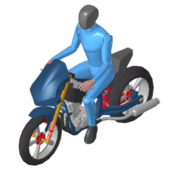
- Full scooter with driver
Figure 17. 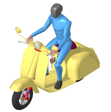
- Full motorcycle with driver
- User/Custom library
- The Custom library allows you to add your own library in MotionView.
Create a Full Vehicle with Driver
In this step, you will learn how to create a full vehicle model with driver using the Car/Small truck library. Using this library, you can build a parameterized model with a variety of different configurations to choose from.
-
From the Vehicle Tools ribbon, click on the
Libraries tool displayed in the Modeling group, to invoke the Set
wizard library dialog.
- Select the Car/Small truck library and click OK.
-
In the same group, click on Assembly
 to invoke the selection wizard.
-
Select Full vehicle with driver from the wizard and
select Next.
Figure 18. Select the Model Type 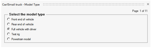
-
Click on the Front Wheel Drive option for the driveline
configuration and select Next to access the Primary
Systems page.
Figure 19. Select Driveline Configuration 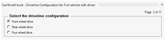
-
In the Primary Systems page, as shown in the figure below, you can configure
the main systems present in the vehicle:
- From the Front suspension drop-down menu, you can select between 5 different variations of front suspension types.
- From the Steering linkages drop-down menu, you can choose between 3 different steering geometries.
- From the Rear suspension drop-down menu, you can browse between a set of 11 different suspension configurations.
- From the Powertrain drop-down menu, you can access four different powertrain types, such as the IC engine with friction clutch or automatic transmission, linear and electric motor powertrain.
Choose the default options and click Next.Figure 20. Select Primary Systems Page 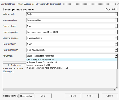
- In the following pages of the wizard there are numerous options to configure the vehicle’s subsystems. Click Next, to browse between the available pages of the wizard to consider your configuration options.
- You also have some sophisticated control systems at your disposal, to improve the vehicle’s dynamic performance. Such systems are the Traction Controller, ABS and ESP.
- In the last page of the wizard, the option for the Driver System comes as a prerequisite in every vehicle model’s creation. The Altair Driver is responsible for the control of throttle, brake and steering inputs according to the requested outputs.
-
Finally, click Finish to complete setting up your model.
A full vehicle model with driver now appears in your modeling window, as shown
in the figure below.
Figure 21. Full Vehicle Model with Driver in MotionView 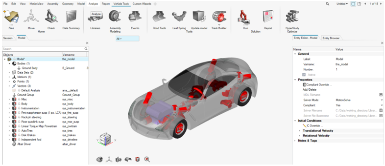
Modify the Model
In this step, you will learn how to modify the vehicle model created in the previous step.
- From the Body system, you can alter vehicle body’s graphics, properties (such as mass), inertias and shift its center of gravity.
- From the Front and Rear suspension systems, you are able to modify suspension components’ properties and geometry, by changing their inertial properties and the chassis hardpoints. Additionally, you can change the spring-damper stiffness and damping properties, or even import your own suspension components to replace the existing ones.
- From the Powertrain system, you can change the engine’s specifications, mass and inertias properties, its bushings stiffness and damping and the drivetrain’s characteristics.
- Tires system enables you to modify all tire related features, such as dimensions, mass, inertias and choose from a wide range of tire files supported in MotionSolve.
- In Disk Brakes system, you can set-up the disk brakes’ properties.
Add a Driver Event
In this step, you will learn how to add and set up a driver event.
-
From the Vehicle Tools ribbon, click on
Events
 to open the Entity Browser folder of Events.
-
From the Entity Browser, double-click on
Double Lane to add the event in the model.
Figure 22. Entity Browser - Double Lane Event 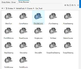
- Open the Entity Editor to access the event’s parameters.
-
From Parameters section, retain the
Units option to
Model. -
Increase Length- Section 1-5 to
25000as shown in the figure below.Figure 23. Event Parameters 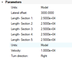
-
Optionally, you have access to additional control, signal, road and simulation
settings through the event’s Entity Editor.
Specifically:
- The Controller settings section is used to tune the controller for path following.
- The Signal settings section is used to apply limitations to driver’s inputs.
- The Road settings section enables you to incorporate various road types.
- The Simulation settings section provides access to numerical integration settings.
Run a Model Simulation
In this step, you will simulate the vehicle model in a double-lane change event.
-
Click the Check Model button
 in the Home group to check the model for
errors.
If it contains errors, an error notification will appear in the message log below the model.
in the Home group to check the model for
errors.
If it contains errors, an error notification will appear in the message log below the model. -
From Vehicle Tools ribbon, click on the
Analysis settings icon
 on the Run ribbon.
-
In the Run Motion Analysis window:
-
Specify an Output directory such as your
<working directory>, where the results files
will be saved.
Figure 24. Run Motion Analysis Window 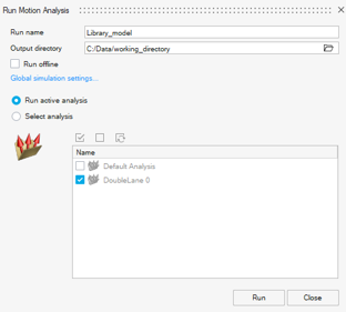
Note: Upon clicking Run, the Run Status dialog is invoked showing a live run status. The modeling window displays a live animation of the model while it is being solved by MotionSolve.Select the Run Offline option to run the model in MotionSolve and post-process the results using HyperView and HyperGraph.
-
Specify an Output directory such as your
<working directory>, where the results files
will be saved.
View the Results
In this step, you will learn how to use Reports to display results.
-
From the Vehicle Tools ribbon, click on the
Report tool
 , in the Solution group.
-
In the View Reports dialog, select the newly generated report and click
OK.
Figure 25. View Reports Dialog 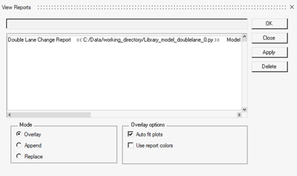
Note: After generating the report, several new pages containing useful information on the simulation results are added to the session. From here, you can review the vehicle’s overall performance regarding the suspension, traction and engine capabilities while considering accelerations and driver inputs. - The first page of the report includes the event’s animation. Click Play to animate the results.
-
Finally, browse the next pages to view the plots automatically generated by the
report.
Figure 26. Vehicle’s Lateral Acceleration, Steering Wheel Inputs and Engine Torque 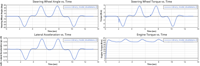
Figure 27. Suspension Travel Results 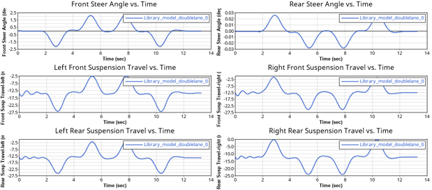
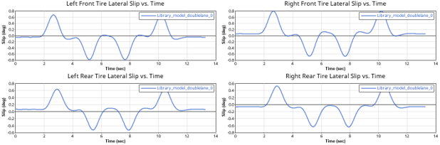
Figure 28. Tire Lateral Slip Results