In this tutorial you will learn how to modify the road property file and road
reference marker to position a cleat road in a single tire model.
Introduction
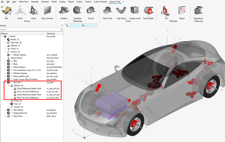
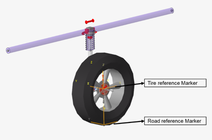
Road reference marker is the coordinate system that is used by MotionSolve to evaluate the position and
orientation of the road. The road file will be evaluated with respect to
the road reference marker which is also included in the Tire entities
selectors.Figure 1. Road reference markers used to orient the tire
Road Reference Marker - Cleat Road Model
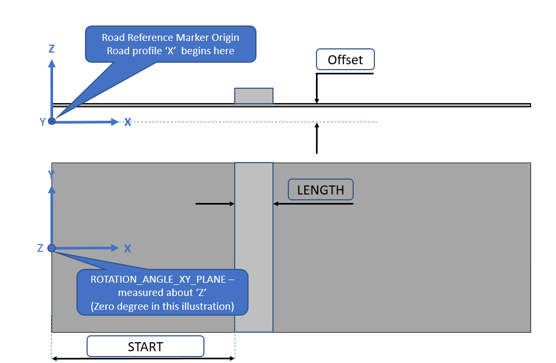
The Cleat Road is represented by a flat road with a single cleat (cuboid
obstacle) that can be oriented in perpendicular or oblique direction
related to the X-axis of the Road Reference Marker.Figure 2. Cleat Road Oriented by the Road Reference Marker
In the road property file, Offset is the distance of the
ground with respect to the Z-axis of the Road Reference Marker.
Length measures the width of the cleat along
X-axis. Rotation angle XY plane is the positive X-axis
of the road with respect to the inertial frame. Start
indicates the distance along the X-axis of the road from the origin to
the start of the cleat.
In this tutorial you will learn how to modify the road property file and
road reference marker to position the cleat road in a single tire model.
By plotting the tire forces versus the tire patch location, you will
understand the influence of the marker and road property in the
simulation results.
Files Required
Before you begin, copy the file(s) used in this tutorial to your
working directory.
From the Start menu, select Altair2024 > MotionView2024.
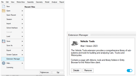
Click File > Extension Manager and use the slider to load the Vehicle
Tools Extension.
Figure 3.
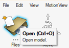
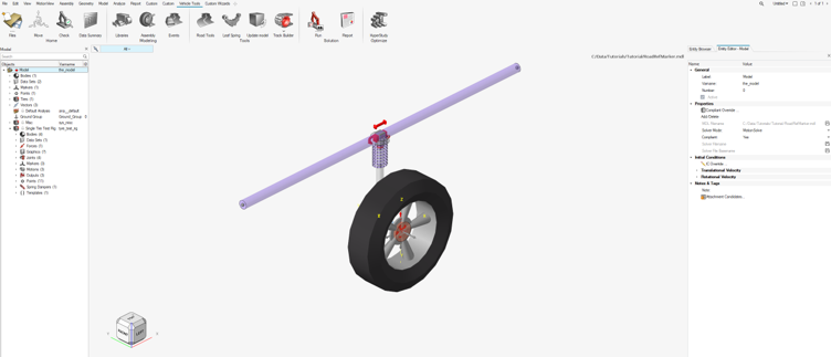
Click Open and load the
RoadRefMarker.mdl file.
Figure 4. The model is displayed in MotionView.Figure 5.
Note that the Road Reference marker is located at the contact patch of
the tire.Figure 6.
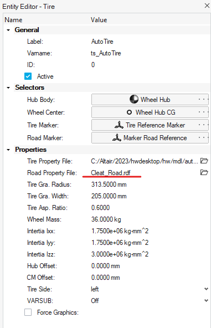
Using the Entity Editor, load the
Cleat_PlankRoad.rdf file as the Road property
file.
Figure 7.
The parameters available in the road property file are shown below.
$--------------------------------------------------------------------------UNITS
[UNITS]
LENGTH                  = 'mm'
FORCE                   = 'newton'
ANGLE                   = 'degree'
MASS                    = 'kg'
TIME                    = 'sec'
$--------------------------------------------------------------------------MODEL
[MODEL]
PROPERTY_FILE_FORMAT    = 'USER'
FUNCTION_NAME 	= 'mbdtire::ROAD_ALTAIR'
METHOD   	=  '2D'
ROAD_TYPE  	= 'pot_hole'
$-----------------------------------------------------------------------GRAPHICS
[GRAPHICS]
ROAD_INCR = 10
$---------------------------------------------------------------------PARAMETERS
[PARAMETERS]
MU                      =   1.0  $ peak friction scaling coefficient
OFFSET                  =     0  $ vertical offset of the ground wrt inertial frame
DEPTH                   =   -25  $ height of the cleat if negative otherwise it is depth
ROTATION_ANGLE_XY_PLANE =     0  $ definition of the positive X-axis of the road wrt inertial frame
START                   =     0  $ distance along the X-axis of the road to the start of the cleat
LENGTH                  =    50  $ length of the cleat (excluding bevel) along X-axis of the road
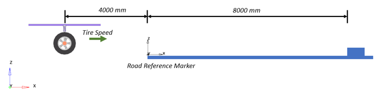
Change the START Parameter in the Road File and Verify the Results
In this step, the road start point will be shifted 4000mm
along X in the property file, however in MotionView the Road
Reference Marker remains at the same position.
Change the START parameter to 4000 in the
Cleat_Road.rdf file using a text editor and save the
change.
$---------------------------------------------------------------------PARAMETERS
[PARAMETERS]
MU                      =   1.0  $ peak friction scaling coefficient
OFFSET                  =     0  $ vertical offset of the ground wrt inertial frame
DEPTH                   =   -25  $ height of the cleat if negative otherwise it is depth
ROTATION_ANGLE_XY_PLANE =     0  $ definition of the positive X-axis of the road wrt inertial frame
START                   =  4000  $ distance along the X-axis of the road to the start of the cleat
LENGTH                  =    50  $ length of the cleat (excluding bevel) along X-axis of the road
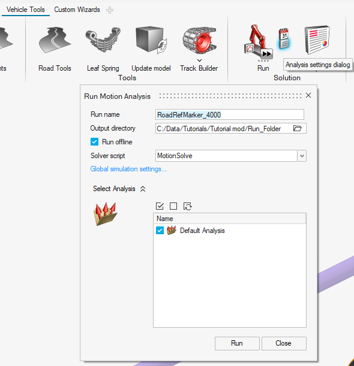
Under Vehicle Tools, click on the Analysis
settings dialog icon (located on the right side of the Run icon)
within the Run ribbon, to open the Run Motion
Analysis window.
Figure 8.
Browse and locate the required file path to save and run the current model.
Specify RoadRefMarker_4000 as the Run name.
Select the Run offline option and click the
Run button.
MotionSolve is invoked in the background and runs
the simulation.
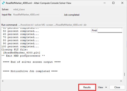
After the MotionSolve run is complete, click on
Results.
A new window with HyperView will open and the
animation of the model can be visualized. Figure 9.
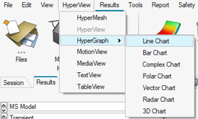
Open a HyperGraph > Line
Chart session from Client selection menu.
Figure 10.
Click on open and load the .plt file saved in the MotionSolve simulation.
Figure 11.
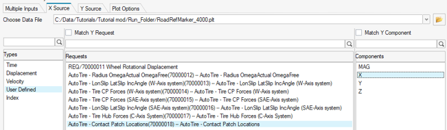
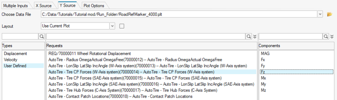
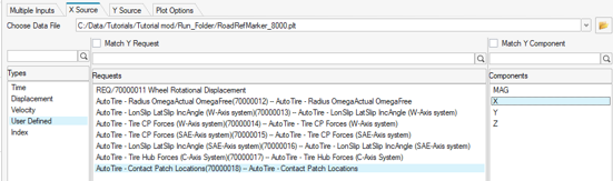
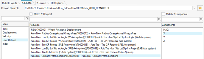
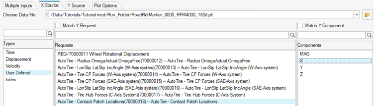
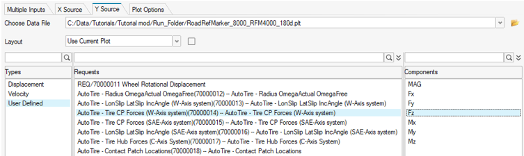
Define the X-axis by clicking on X Source and selecting
the following options.
Click the Plot button to obtain the following
plot.
Figure 14.
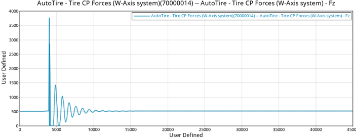
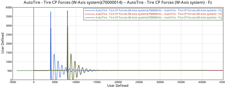
The plot displays the Tire force (Z-axis) vs Contact patch location. The
curve indicates the oscillation starting at 4000mm along the X-axis, meaning
the tire reaches the obstacle at 4000mm.
Change the START Parameter to 8000 in the Road File and Verify the Results
In this step, the road start point will be shifted 8000mm
along X in the property file keeping the Road Reference Marker at the same
position.
Change the START parameter to 8000 in the
Cleat_Road.rdf file using a text editor and save the
change.
$---------------------------------------------------------------------PARAMETERS
[PARAMETERS]
MU                      =   1.0  $ peak friction scaling coefficient
OFFSET                  =     0  $ vertical offset of the ground wrt inertial frame
DEPTH                   =   -25  $ height of the cleat if negative otherwise it is depth
ROTATION_ANGLE_XY_PLANE =     0  $ definition of the positive X-axis of the road wrt inertial frame
START                   =  8000  $ distance along the X-axis of the road to the start of the cleat
LENGTH                  =    50  $ length of the cleat (excluding bevel) along X-axis of the road
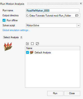
In MotionView, open the Run Motion Analysis dialog
and specify RoadRefMarker_8000 as the Run name.
Click the Run button to initialize the simulation.
Figure 15.
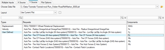
In the same HyperGraph session, click on open and
locate the newRoadRefMarker_8000.plt file.
Click the Plot button to visualize the two plots
overlayed.
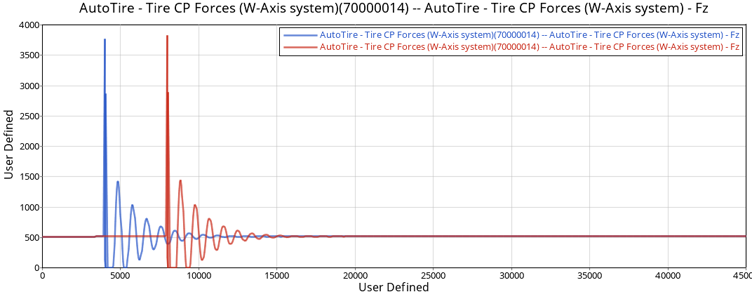
Figure 18.
The plot shows the modifications on Start parameter in the Road Property
File. The blue curve indicates the obstacle at 4000mm along the X-axis,
while the red curve shows the obstacle at 8000mm.
Change the Road Reference Marker Position and Verify the Results
In this step, the Road Reference Marker will be positioned
4000mm along X keeping the Road Property File with a Start parameter of
8000mm.
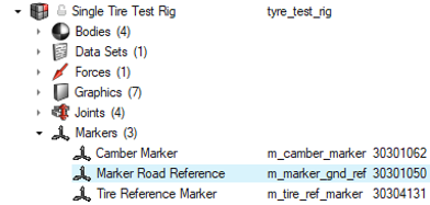
In MotionView, select the Marker Road
Reference in the Model Browser and check the
parameters using the Entity Editor.
Figure 19.
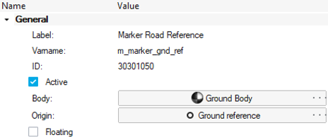
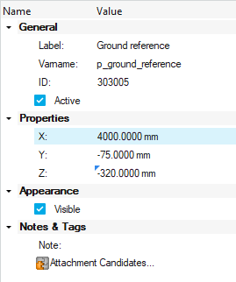
The Road Reference Marker's origin uses the Ground reference point.Figure 20.
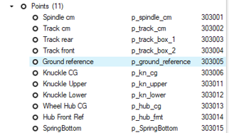
Select the Ground reference point from the Model Browser and change the X coordinate value to
4000 using theEntity Editor.
Figure 21.
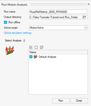
From the Run Ribbon, open the Run Motion Analysis
window, specify RoadRefMarker_8000_RFM400 as the
Run name, and click on the
Run.
Figure 22.
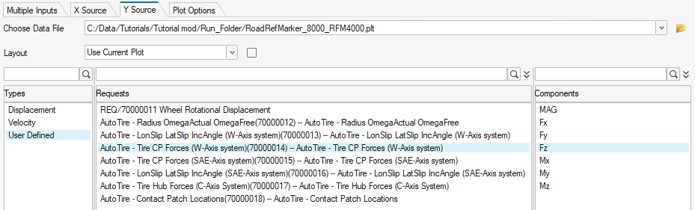
In the HyperGraph session, click on open and locate
the RoadRefMarker_8000_RFM400.plt file.
Click the Plot button to visualize the three plots
overlayed.
Figure 25.
The green curve shows the results of modifying the Road Reference Marker
4000mm keeping the start at 8000mm. You may notice that plot indicates the
obstacles at 8000mm as in Step 3, but the starting point is not 0mm as
before but -4000mm in X. The explanation for this is shown in the image
below. The Road Reference Marker works as the reference for the road, since
the marker was moved, the contact patch is now behind the reference, hence
starting at a negative value.Figure 26.
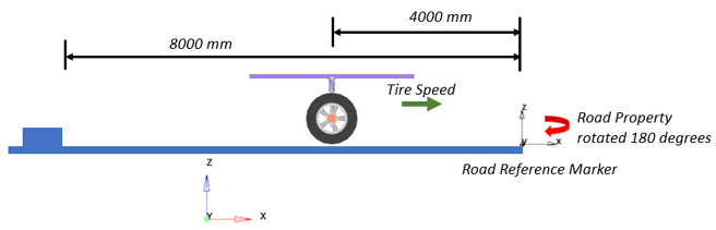
Change the Rotation Angle XY Plane to 180 and Verify the Results
In this step, the Road Property File will be rotated 180
degrees using Rotation Angle. Keep the Road Property File Start parameter at 8000 mm and
the Road Reference Marker positioned at 4000 mm along X.
Change the ROTATION_ANGLE_XY_PLANE parameter to 180 in the
Cleat_Road.rdf file using a text editor and save the
change.
$---------------------------------------------------------------------PARAMETERS
[PARAMETERS]
MU                      =   1.0  $ peak friction scaling coefficient
OFFSET                  =     0  $ vertical offset of the ground wrt inertial frame
DEPTH                   =   -25  $ height of the cleat if negative otherwise it is depth
ROTATION_ANGLE_XY_PLANE =   180  $ definition of the positive X-axis of the road wrt inertial frame
START                   =  8000  $ distance along the X-axis of the road to the start of the cleat
LENGTH                  =    50  $ length of the cleat (excluding bevel) along X-axis of the road
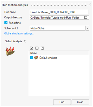
In MotionView, open the Run Motion Analysis dialog
and specify RoadRefMarker_8000_RFM4000_180d as the Run
name. Click the Run button to simulate the model.
Figure 27.
In the HyperGraph session, click on open and locate
the RoadRefMarker_8000_RFM4000_180d.plt file.
Click the Plot button to visualize the four plot
overlayed.
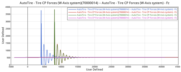
Figure 30.
The pink curve shows the results of rotating the Road Property File 180
degrees. It can be observed that there are no oscillations and the tire does
not reach the obstacle. The explanation for this is shown in the image
below. When rotating the road, the cleat moves behind the tire and opposite
to the tire direction.Figure 31.