Tutorial Level: Advanced In this tutorial, you will learn about the set-up and co-simulation of MotionSolve and EDEM through MotionView.
MotionSolve has the ability to interface with AltairEDEM, a state-of-the-art bulk material simulation tool.
EDEM is based on the Discrete Element Method (DEM)
that simulates and analyzes the behavior of bulk materials such as sand, granules,
capsules, grass, rock masses, and so on. For more information about this method
refer to https://www.altair.com/edem/
and the Discrete Element Simulation in MotionSolve
topic in the MotionSolve User Guide.
This tutorial assumes minimum knowledge in both Altair’s
MotionSolve/MotionView
and EDEM.
Requirements
The following pre-requisites are necessary for a successful interaction
between MotionSolve and EDEM:
Note: It is recommended to
install EDEM in the
same location as MotionSolve (default:
C:/Program Files/Altair/2026).
If EDEM is installed in a
different location, please add
~install_location/EDEM/bin
and
~install_location/EDEM/lib to
the PATH environment variable for features such as
geometry transfer and co-simulation to work
effectively.
The steps and options described
here are for the version 2024 release of HyperWorks and EDEM.
Problem Definition
The problem consists of a wheel, that can only rotate around its center.
A number of particles is impinged on the wheel blades, causing it to
rotate. The wheel is modeled in MotionSolve,
while the particles and its interaction with the wheel is modeled in
EDEM. A rigid wheel to particle
interaction is set up first. The wheel is later replaced with a flexible
body to show flexible body to particle interaction.
Both the wheel and the particle data are given in the table below:
Property
Units
Values
Particles
(Bulk material)
Radius
[m]
0.10
Poisson's ratio
[-]
0.25
Density
[kg/m3]
2500
Shear Modulus
[Pa]
108
Wheel
(Equipment material)
Poisson's ratio
[-]
0.30
Density
[kg/m3]
7860
Shear Modulus
[Pa]
8.077e.1010
Before you begin, copy the file(s) used in this tutorial to your
working directory.
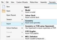
From the menu bar, navigate to File > Import and click on Geometry in the drop-down
menu.
Figure 1. Import Geometry
Locate and select the wheel.step file from your
<working directory> and click
Open.
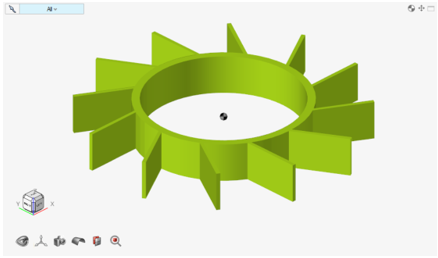
The wheel geometry is imported into MotionView.Figure 2. Model in MotionView after wheel geometry
import
From the Ribbon, select Model and click on the
Joints icon
from the Entities toolbar.
The Joints guide bar is displayed.
Select the wheel and Ground Body
to resolve the Body 1 and Body 2 collectors respectively, by clicking on the
ellipsis
next to each collector.
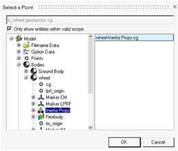
Similarly, use the Select a Point dialog (by clicking on the ellipsis) to
resolve the Point collector of Origin by choosing Bodies > wheel > Inertia Props and select wheel-Inertia Props-cg.
Figure 3. Joints guide bar Figure 4. Select a Point Dialog to Select the CG of the Wheel Body
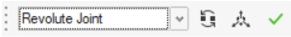
Click Create.
Using the microdialog, select Revolute
Joint from the drop-down menu.
Figure 5. Select Joint Type
Navigate to the Entity Editor to ensure that the
Orientation method is set to Vector and the vector is
Global Z.
Click to finish editing.
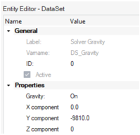
From the Model Browser > Data Sets
folder, select the Solver Gravity dataset and navigate to
the Entity Editor to set the Y component to
-9810 and the Z component to
0.0.
Figure 6. Dataset - Solver Gravity
Save the model as wheel.mdl.
Set Up the EDEM Model
Next, you will set up the EDEM
model. EDEM modeling for this example broadly assumes the
following steps that are detailed out further below:
Define a bulk material
Define a particle shape
Define an equipment material
Define the equipment geometry
Define a virtual geometry/particle factory
Define environment parameters
Define the simulation options
Launch EDEM.
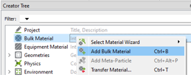
In the Creator Tree, right-click on Bulk Material and
select Add Bulk Material.
Figure 7. Add Bulk Material
A new material named 'BulkMaterial 1' is created.
Leave the material properties unchanged.
Click on the + sign under
Interaction, on the BulkMaterial 1
Properties menu.
Select BulkMaterial 1 in the pop-up window.
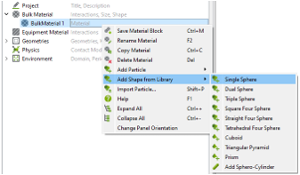
In the Creator Tree, right-click on BulkMaterial 1
(which was just added) and select Add Shape from Library > Single
Sphere.
Figure 8. Add Single-Sphere Shape
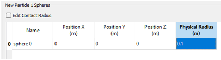
Set the Physical Radius (m) to
0.1.
Figure 9. Particle Sphere Properties
Optional: Due to the change in particle size, you can reset/fit the view of
the particle by selecting on the View panel.
Go to Properties under the New Particle
1 in the Creator Tree and select Auto
Calculation.
Particle geometry is now defined. Next, you will define the equipment material
which represents the material properties for the wheel in EDEM.
In the Creator Tree, right-click on Equipment Material
and select Add Equipment Material.
Figure 10. Add Equipment Material
A new material named 'EquipMaterial 1' is
created.
Change the Solids density() to 7860 and
Shear Modulus(G) to
8.077e10.
Click on + under Interaction.
In the pop-up window, click OK for
BulkMaterial 1.
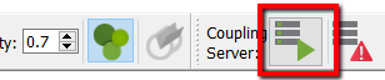
From the toolbar on the top, click on the Start Coupling
Server icon to turn on the coupling server.
Figure 11. Turning on the Coupling Server This setting allows coupling with MotionView
and MotionSolve.
Return to MotionView and click on the
EDEM Subsystem icon from the Assembly
ribbon.
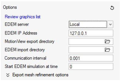
In the panel that appears, click on
to invoke the Options dialog and define the EDEM server.
Figure 12. EDEM guide bar
For EDEM server, choose between Local or
Remote from the drop-down menu. Select
Local if EDEM and MotionView/MotionSolve are on the same machine. Select Remote if
EDEM resides on a different
machine.
Figure 13. Options Dialog
If Remote has been selected, you will have to
define the settings for the remote co-simulation, which are defined in
the Bulk Material Interaction
topic.
Click on again to exit the Options dialog.
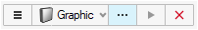
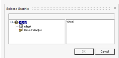
Verify that the Graphic option is selected from
the drop-down menu and click on the Graphic
Advanced Selector to select the wheel graphics.
Figure 14. Select Wheel Graphics
Click on the Transfer and Create
System button. If the transfer is successful, a confirmation
message is displayed in the message log. Close the message log.
A system called 'DEM 0' is added to the MotionView model. This system contains all the necessary
entities for MotionSolve to simulate with
EDEM.
Save the model .
Switch to the EDEM graphical user interface.
Once the import process is complete, click on the drop-down menu within the
View section on the toolbar and select the
-Z view and zoom in.
Figure 15. View Section
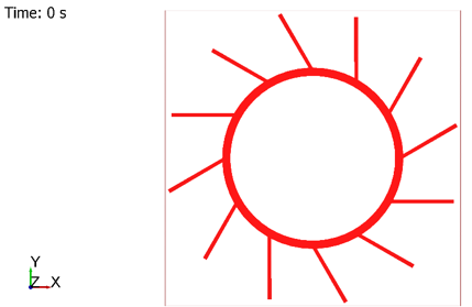
The graphic screen should appear as shown below:Figure 16. Wheel Geometry in EDEM
Observe the component under Geometries in the
Creator tree. The wheel has the name ‘wheel’, like the body name in MotionView.
Next, you will set up the geometry for the particle factory.
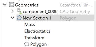
In the Creator Tree, right-click on Geometries and
select Add Geometry and then
Polygon.
A geometry with the name 'New Section 1' is
added.
Change the Type from Physical to
Virtual.
Figure 17. Polygon Geometry for the Particle Factory
Select Transform under 'New Section 1' and set the
following properties:
Position
Rotation
X
1.6
1.5708
Y
1.7
0
Z
0
0
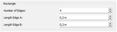
Select Polygon under 'New Section 1' and set the
following properties.
Length
Edge A
0.2
Edge B
0.2
Figure 18. Polygon properties
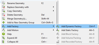
Right-click on New Section 1 and select Add Factory > Add Dynamic Factory.
Figure 19. Add Dynamic Factory
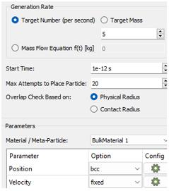
Set the Target number (per second) equal to
5.
Set bcc in Position.
Figure 20. Adding Factory
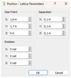
Click on the gear icon to display the Position - Lattice Parameters
dialog.
Under Start Point, set X and
Y to 1.6 and
1.7 respectively.
Leave the remaining fields set to the default values.
Figure 21. Position - Lattice Parameters
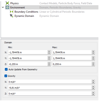
In the Creator Tree, select Environment and Under
Gravity set Y to -9.81 and
Z to 0.
Figure 22. Setting Gravity
Save the model as wheel.dem using the
File menu or Save icon on the
top toolbar.
Simulation Set Up in EDEM
Switch to the Simulator.
Figure 23. Simulator Icon on the Toolbar
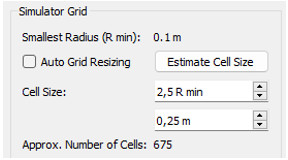
Click on Estimate Cell Size in the Simulator Grid menu
and accept the derived cell size.
Figure 24. Estimating Cell Size
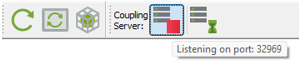
Confirm that the Coupling Server is on.
Figure 25. Coupling Server Icon
Tip: Hovering over the icon should show a tool
tip text similar to “Listening on port 32969”.
The EDEM model is now ready to
simulate with MotionSolve.
Run the Simulation
In MotionView, navigate to the Model Browser, click on Default Analysis
and change the following settings using the Entity Editor:
From the Analysis Parameters section, change the End
time to 10.
From the Dynamics Settings section, set Maximum step
size to 0.001.
From the Ribbon, select Analyze and go to Run > Analysis settings to invoke the Run Motion Analysis dialog.
Set a Results folder and the Run name.
Click on the Run button to start the simulation.
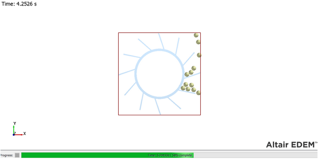
MotionSolve is invoked and the simulation should
also begin on EDEM side. The simulation process
should also be visible in EDEM.Figure 26. EDEM Graphic Screen During
Simulation
In EDEM, click on Auto
update on the top toolbar to update the graphic visualization as
the simulation progresses.
Figure 27. Auto Update
Once the simulation is complete, close the Message Log in MotionView and the MotionSolve solver window.
Post-processing
For components that are interacting in EDEM, the
animation can be visualized in EDEM through the Analyst
page.
Click on the Analyst icon in the toolbar.
Figure 28. Analyst Icon on the Toolbar
Reset the animation with the toolbar at the bottom right.
Figure 29. Animation Bar in EDEM
Click the Animate Forwards icon .
Switch back to Creator and save the EDEM model
using File > Save.
Translate EDEM particle results to HyperView H3D.
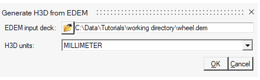
In MotionView, from the search bar on the
top right, search and select Generate H3D from EDEM results.
Provide the wheel.dem file that was saved in
EDEM as input and ensure that the units
are correct (millimeters).
Click OK.
Figure 30. H3D Generation from EDEM
Results
On Windows, a command window is displayed, showing the progress
of converting particle information into H3D. The file
wheel_edem.h3d is generated.
Visualize the animation in HyperView.
Open a new HyperView page.
Click the Open icon to load the MotionSolve H3D result in a HyperView window and click
Apply.
In HyperView, select the
Overlay check box in the Load Model
panel.
Use the Open Model file browser to locate and select the
wheel_edem.h3d file from the working
directory.
Click Apply (answer Yes
to the pop-up warning message).
Animate using the Start/Pause Animation button
.
Figure 31. Rigid Wheel Body Co-simulation Animation
Note: Since geometries are represented in both MotionSolve and EDEM, the
overlay would show duplicate geometries.
Flexible Body Coupling
Setting up and running a co-simulation with a flexible body follows the same steps as
those performed with a rigid body in the previous step.
Note: A flexible body
interaction can be set up directly. There is no need to do its rigid body
interaction first.
An equivalent flexible body H3D file of the wheel is available,
flex_wheel_flex_blades.h3d (previously copied to your
working directory).
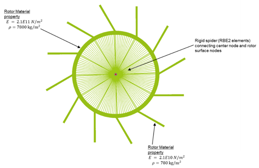
Figure 32. Flexible Body
The flexible body is created with the following features:
The rotor elements are assigned the material property steel.
The blade element material has a material with 10% of Modulus of elasticity
and density as steel.
The center node is connected to the nodes on the inner surface of the rotor
using rigid (RBE2 elements).
The center node and a node on each blade (arbitrary) has been selected as
interface nodes for an adequate modal representation.
From MotionView's Model Browser, select DEM system (DEM_0) and deactivate it through
the right-click context menu Deactivate > Selected only.
Select the body (wheel) from the Model Browser or through the modeling window.
From the Body panel, select the Flex Body (CMS) check
box.
Browse to select the flexible body H3D file
flex_wheel_flex_blades.h3d from your
<working directory>.
Observe that the same file is selected as Graphics File.
Click on the Nodes & Modes... button.
From the Nodes tab, find a node in the flexible body corresponding to the
center joint location by clicking Find after selecting
the row entry for the Joint Marker.
Close the dialog.
In EDEM, from the Creator
context, reset the time to 0 s by clicking .
Under Geometries, select the wheel geometry and delete
it.
Save the EDEM file as
wheel_flex.dem.
In MotionView, bring up the EDEMguide bar by clicking its icon from the Assembly
ribbon.
Change the collector to Body collector. Pick the
wheel [Flex body].
Click Transfer and Create System.
The flex body should be transferred to EDEM.
A new DEM system is also created in MotionView
Click on the Run analysis settings button , located near the Run icon on the Analyze tab of
the ribbon.
Change the Run name to
wheel_flex.
Click Run.
Once the run is complete, follow the procedures mentioned above in Post-processing Steps #4 and #5, to
visualize the results.
 from the Entities toolbar.
The Joints guide bar is displayed.
from the Entities toolbar.
The Joints guide bar is displayed. next to each collector.

 .
.
 to finish editing.
 as wheel.mdl.
 on the View panel.
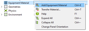
 ) to 7860 and
Shear Modulus(G) to
8.077e10.
) to 7860 and
Shear Modulus(G) to
8.077e10.
 from the Assembly
ribbon.
from the Assembly
ribbon.
 to invoke the Options dialog and define the EDEM server.
 to select the wheel graphics.
 the Transfer and Create
System button. If the transfer is successful, a confirmation
message is displayed in the message log. Close the message log.
A system called 'DEM 0' is added to the MotionView model. This system contains all the necessary entities for MotionSolve to simulate with EDEM.
the Transfer and Create
System button. If the transfer is successful, a confirmation
message is displayed in the message log. Close the message log.
A system called 'DEM 0' is added to the MotionView model. This system contains all the necessary entities for MotionSolve to simulate with EDEM.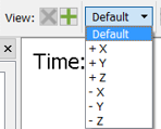
 to display the Position - Lattice Parameters
dialog.
to display the Position - Lattice Parameters
dialog.


 .
.
 and save the EDEM model
using .
and save the EDEM model
using .
 to load the MotionSolve H3D result in a HyperView window and click
Apply.
to load the MotionSolve H3D result in a HyperView window and click
Apply.
 .
.

 .
.
 .
The flex body should be transferred to EDEM. A new DEM system is also created in MotionView
.
The flex body should be transferred to EDEM. A new DEM system is also created in MotionView , located near the Run icon on the Analyze tab of
the ribbon.
, located near the Run icon on the Analyze tab of
the ribbon.