Connecting Rod as a Flexible Body
Tutorial Level: Intermediate This tutorial will help you learn to work with flexible bodies in MotionView.
- Introduction to flexible bodies
- FlexPrep – Flexible Body Generation tool
- Creating a flexible body
- Adding a flexible body to a model
- Solving and post-processing
Introduction to Flexible Bodies
Traditional multibody dynamic (MBD) analyses involve the simulation of rigid body systems under the application of forces and/or motions. In the real world, a body deforms under the application of force. Rigid body simulations do not capture such deformations, and this may lead to inaccurate results. Inclusion of flexible bodies in MBD simulations accounts for flexibility.
- Capture body deformation effects in simulations
- Acquire greater accuracy in load predictions
- Study stress distribution in the flexible body
- Perform fatigue analysis
What is a Flexible Body?
- A flexible body (flexbody for short) is a modal representation of a finite element (FE) model. The finite element model is reduced to a representation with very few modal degrees of freedom through a reduction process called Component Mode Synthesis (CMS) by a FE solver such as Altair/OptiStruct.
- Finite element models have a very high number of degrees of freedom. It is hard for MBD solvers to handle these.
- The nodal displacement in physical coordinates is represented as a linear
combination of a small number of modal coordinates.
where:
is nodal displacements vector
is modal matrix
is matrix of modal participation factors or modal coordinates to be determined by the MBD analysis.
- Component Mode Synthesis (CMS) reduces a finite element model to set of orthogonal mode shapes.
Additional details on the theory of CMS for Flexible Body Generation can be found here.
Flexbody Generation Using OptiStruct
- Use the FlexPrep utility in MotionView
- Create the FE model in HyperMesh with assigned material and property cards.
- Export as OptiStruct file (*.fem).
- Use the exported.fem in FlexPrep tool in MotionView.
- Provide additional inputs in FlexPrep.
- FlexPrep will invoke OptiStruct and generate the flexible body (*.h3d) file.
- Use HyperMesh:
- Create the FE model in HyperMesh with assigned material and property cards.
- Create load collector with CMSMETH card.
- Create ASET1 card using Constraints tool.
- Create DTI_UNITS card and Global Case Control CMSMETH.
- Export OptiStruct file (*.fem) and submit it to OptiStruct to generate the flexible body (*.h3d) file.
 |
|||
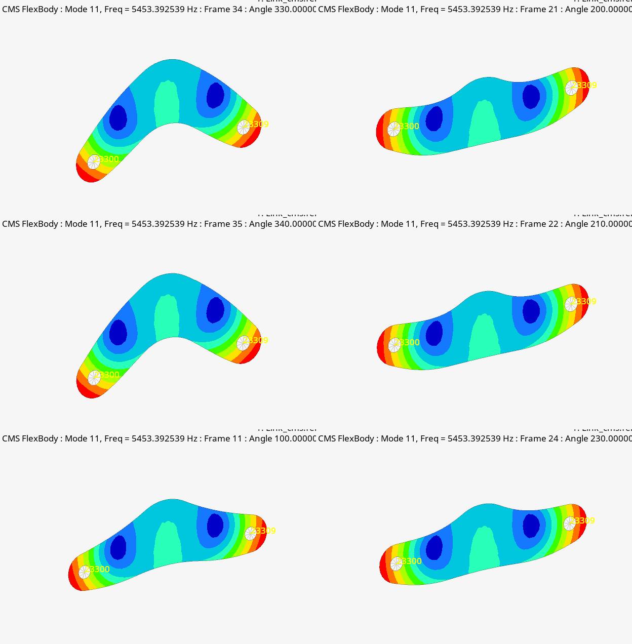 |
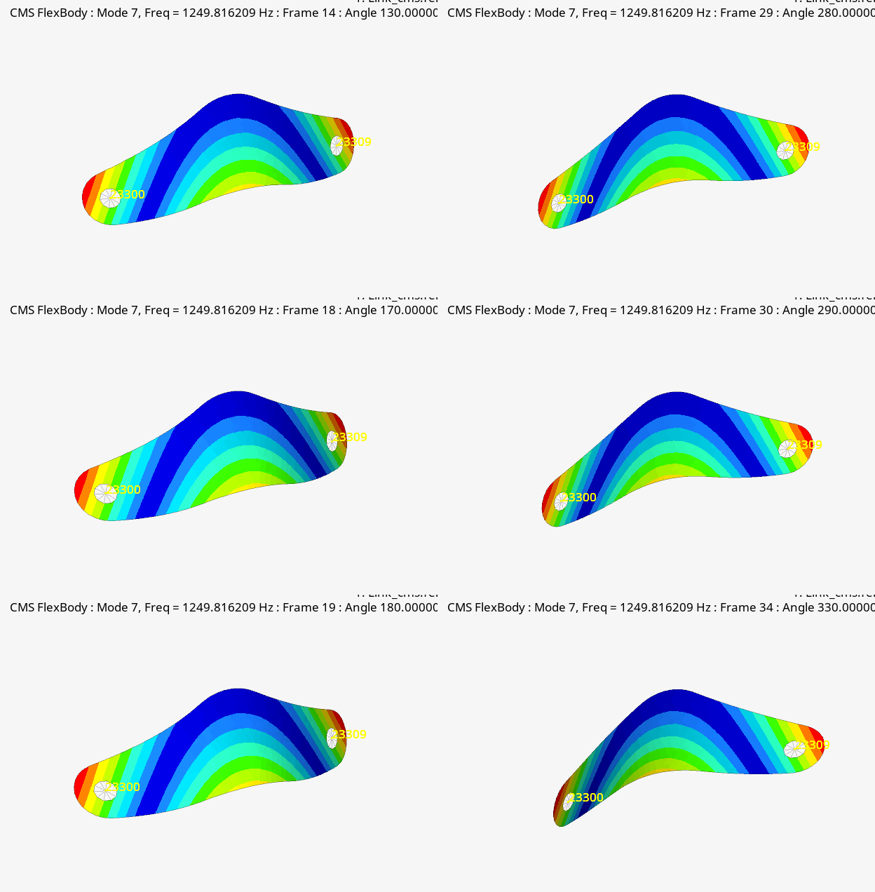 |
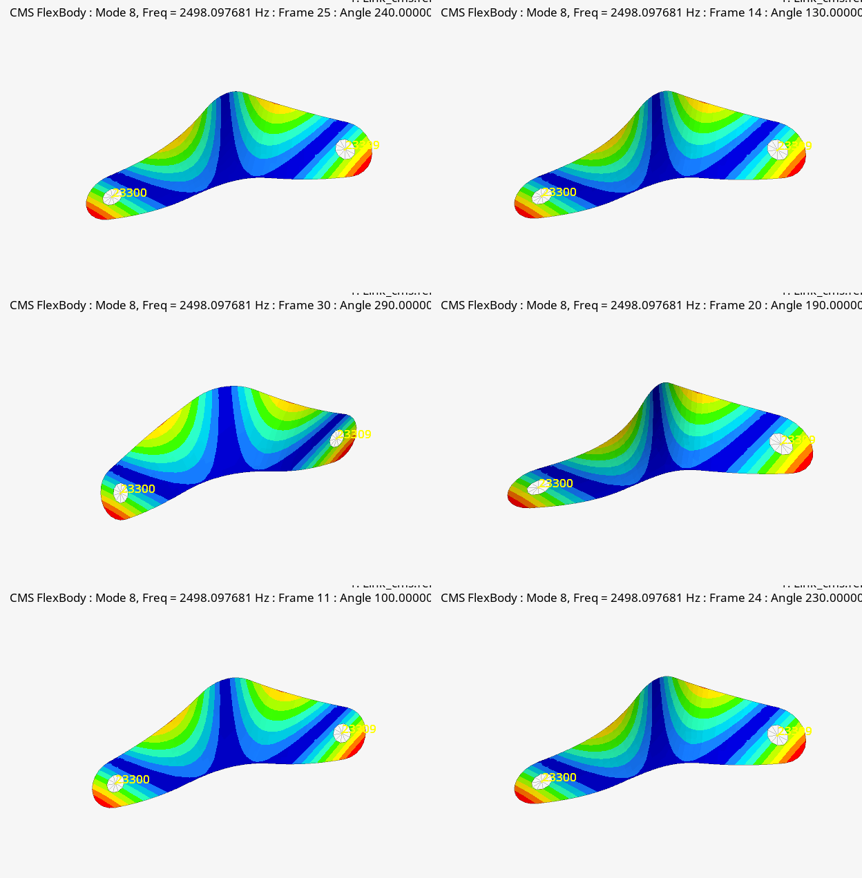 |
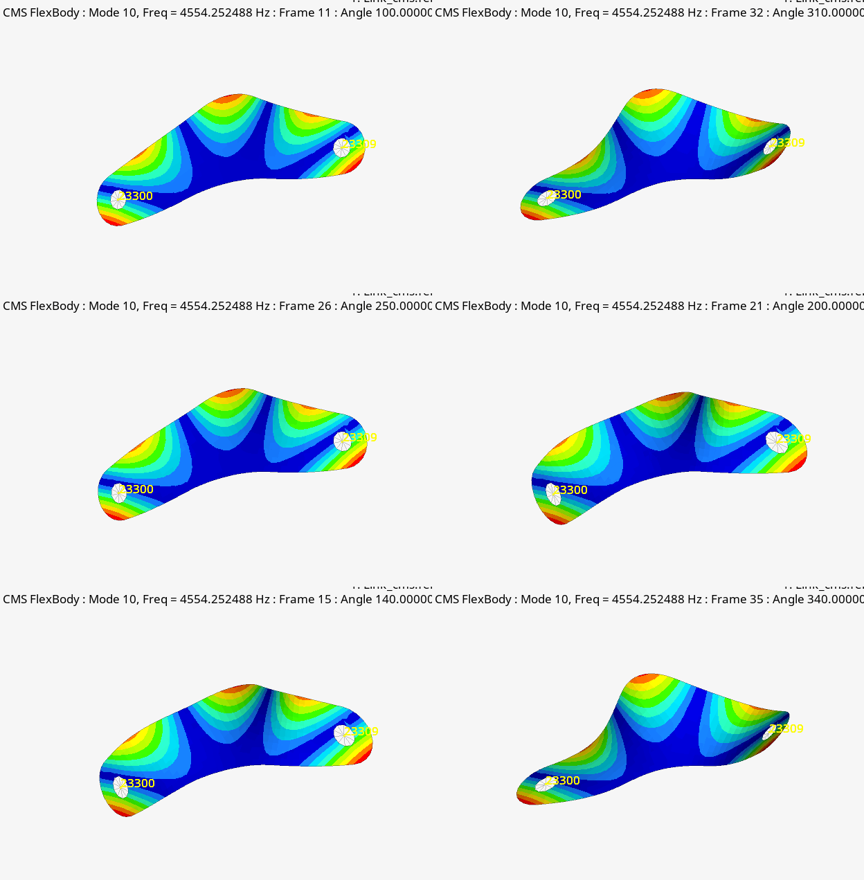 |
- Nodal positions
- Element connectivity
- Eigenvalues of all modes
- Inertia invariants (optional)
- Nodal mass
- Nodal inertia (optional)
- Translational displacement mode shapes
- Rotational displacement mode shapes
- Interface node IDs (optional)
- Element stress/strain tensors (optional)
- Global (rigid) inertia properties (optional)
Using the FlexPrep Utility in the MotionView Interface
FlexPrep is a MotionView utility which facilitates generating a flexible body from a finite element mesh. It also allows mirroring a flexbody and translation between various flexbody formats.
- Mirror an existing flexible body H3D file about a plane
- Translate an MNF file to an Altair H3D file
- Translate an H3D file to an MTX file
- Translate an Altair H3D file to MNF file
- Translate a PCH file to an Altair H3D file
- Translate an Altair H3D file to a DADS DFD file
Once the flexbody H3D is created, it can be used in an MBD model, and the model can be submitted to either MotionSolve or ADAMS.
This tutorial will focus on generating a flex body using the FlexPrep tool in MotionView and using it in a multi-body model solved in MotionSolve.
Exercise: Connecting Rod as a Flexible Body
This exercise shows how to convert an existing rigid body in a model to a flexbody using MotionView.
Generate Flexbody Using FlexPrep Utility
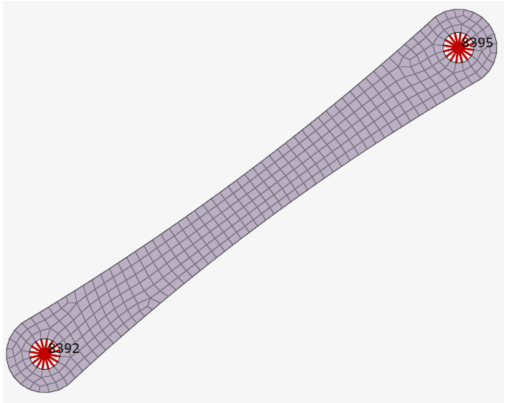
- Start a new MotionView session.
-
From the Analyze ribbon, select the
FlexPrep tool to open the
FlexBodyPrep dialog.
Figure 2. 
Figure 3. 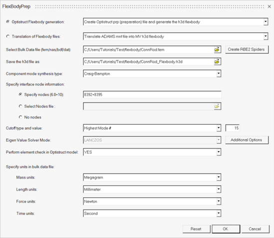
-
From the FlexBodyPrep dialog, verify that
Optistruct Flexbody generation is set to
Create Optistruct prep (preparation) file and generate the h3d
flexbody (default) and retain this selection.
The FlexPrep utility generates an input deck (_prp.fem) for the OptiStruct solver with all the required cards, and then it calls OptiStruct to run the job and create a h3d flexbody to be used in MotionView.
-
Click
 next to Select Bulk Data file (fem/nas/bdf/dat) and
select the input bulk data file ConnRod.fem from your
<working directory>.
-
Click
 next to Save the h3d file as, choose your
<working directory>, and enter the name of the
output h3d file as ConnRod_Flexbody.h3d.
- Verify that Component mode synthesis type is set to Craig-Bampton.
- From the Specify interface node information section, verify that Specify nodes (6:8+10) is selected.
-
Enter 8392+8395 in the Specify
nodes field.
These are interface nodes where constraints or forces are applied in the MBD analysis.Note: If the node numbers are in a range, “:” can be used to provide the nodes in the range. For example, 10001:10004. Node numbers can be specified with combination of “:” (for range) and “+” (individual). For example, 10001:10004+2598+5230:5236.
- Verify that Cutoff type and value is set to Highest Mode # and enter a value of 15.
-
Next to Eigen Value Solver Mode, select Additional
Options button to open the Additional
Options dialog.
Figure 4. 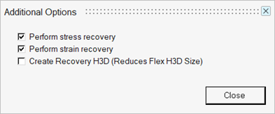
Note: The Create Recovery H3D option is useful in fatigue analysis. A smaller flex H3D file is generated that contains the minimum amount of information required for MBD simulation in MotionSolve. A larger file, *_recov.h3d, is also generated that contains additional information for displacement, velocity, acceleration, stress, and strain. Refer to Recovering MBD Analysis Results in OptiStruct to learn more about using this method for fatigue analysis. -
From the Specify units in bulk data file section, configure the units.
- Set Mass units to Megagram.
- Verify that Length units is set to Millimeter.
- Verify that Force units is set to Newton.
- Verify that Time units is set to Second.
Note: Most often, FE models are created using mm-N-sec as Length-Force-Time units. Mass is a derived unit in FE, hence N-sec^2/mm is equivalent to tonne/mm^3 or MEGAGRAMS. In the given input file, the geometry is in millimeters and the mass density used is in unit Mg/mm^3. Hence, this tutorial uses Megagram as the mass unit as units in bulk data file. Make sure you use consistent units as per the FE model created, or the flexbody generated may have incorrect size or modal frequencies. -
Click OK to launch OptiStruct in a command window.
Based on the inputs provided in the dialog, FlexPrep creates a new FEM file by appending _prp to the input filename (ConnRod_prp.fem) and submits it to OptiStruct. Messages from the FlexPrep translator are displayed in the Output window.
-
Check the status of the OptiStruct run and look for
any error messages in the Output dialog.
Flexbody file ConnRod_Flexbody.h3d gets created in the chosen location and can be used in the next step.
Figure 5. 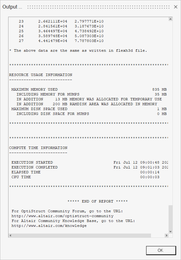
- Click OK in the Output dialog to close it.
Switch From Rigid to Flex
-
Click the Open Model icon
 in the Home group (or use the ), browse to your working directory, and select
mv_intro2_complete.mdl to open the model.
The model is displayed in the modeling window.
in the Home group (or use the ), browse to your working directory, and select
mv_intro2_complete.mdl to open the model.
The model is displayed in the modeling window.Figure 6. 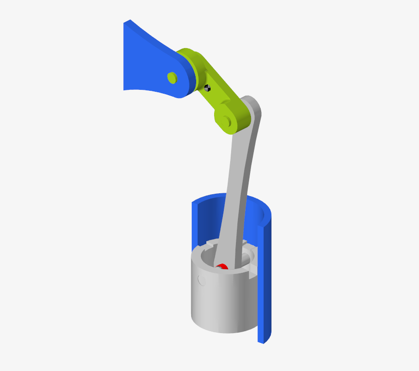
- Select the PistonRod body from the Model Browser or in the modeling window.
-
From the Properties section of the Entity Editor,
select the Flex check box to convert the PistonRod from a
rigid body to a flexbody.
Note: If the Entity Editor is not visible by default, enable it by right-clicking on the PistonRod body and selecting Show Properties option from the context menu.Two new fields, H3D file and Graphic File, appear under the Flex check box.
-
Click
 next to the
H3D file option and select the ConnRod_Flexbody.h3d file
generated in Generate Flexbody Using FlexPrep Utility.
Figure 7. 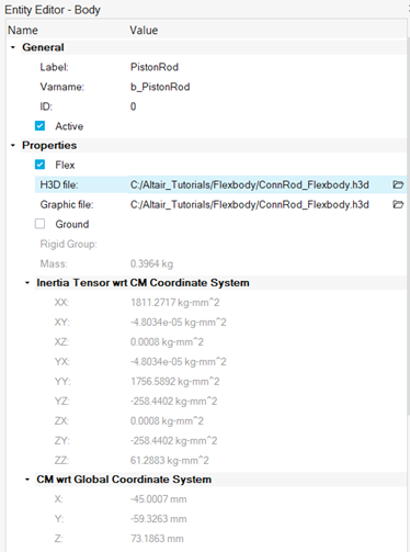
Note: The Graphic File field is automatically populated with the same H3D file. It is possible to provide a different graphic file. This option can be used to provide alternate graphics for the flexbody with reduced size when the original flexbody size is too large. Observe the mass, center of gravity, and inertia properties of PistonRod as a flexbody are similar to that of PistonRod as a rigid body. -
Scroll down and click the Nodes & Modes... button to
open the Nodes & Modes dialog.
Note: The Nodes tab is used to resolve the flexbody's attachments with the parts connected to it. This tab lists all markers of the connections (joints/forces) on the body which is now flexible. These markers can interact with the flexible body only through a node. This tab is used to map each of the markers to a node. The tab also displays the point coordinates of the marker origin.
-
From the Nodes tab, click Find to find nodes on the
flexible body that are located closest to the interface points on the cylinder
model within the tolerance specified in Node
tolerance.
Figure 8. 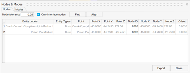
Note: Observe a small offset for both the attachments. It suggests a difference in the coordinate values between the point at which the connections are defined and its corresponding location of the interface nodes. The points can be aligned with the node locations using the Align button. MotionView moves the connection point in the model to the node location on the flexible body. This could affect other entities that reference this point. Hence, this option should be used with caution. Generally, it is common to have minor offsets (values between 0.001mm to 0.01mm). If the offset is more than the tolerance value, MotionView inserts a dummy body between the flexible body and the nearest connection point. If the offset value is too high, it could indicate a mismatch of the FE model information with respect to the MBD model. In such an event, it is recommended to review the models and reconcile the differences.Note: Find and Align actions can be performed on individual attachments by selecting the specific attachment row. -
Select Modes to switch to the Modes tab.
Figure 9. 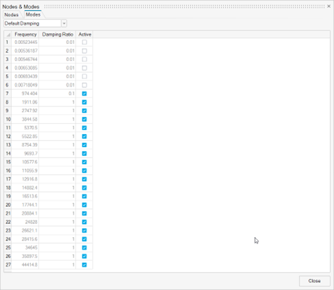
Note: Use this tab to review and select the modes that will be active during the simulation. By default, the rigid body modes are deactivated. Default Damping is used as a standard. With this setting, the solver applies a 1% damping for frequencies under 100Hz. For frequencies greater than 100Hz and less than 1000Hz, 10% damping is used. Modes greater than 1000 Hz use critical damping. - Click the Close button.
-
From the menu bar, select .
- From the Save As Model dialog, browse to your working directory and name the file MV_intro_flexbody.mdl.
- Click Save.
Run and View Results
-
From the Analyze ribbon, select the
Analysis Settings tool from the Run tool group to
open the Run Motion Analysis dialog.
Figure 10. 
- Enter mv_intro_flexbody_Run for Run name and accept the defaults for the remaining settings.
- Click Run.
-
Once the run is complete, click Animate on the
Run Status dialog to review results in HyperView.
Note: A new page gets added to the session with HyperView as an active client. Also, the model with results file of the current simulation is automatically loaded.
-
From the Results ribbon in HyperView, select the Contour tool
to bring up the Contour panel.
Figure 11. 
Figure 12. The Contour Panel 
Tip: If the panel is not displayed, turn it on from the menu bar by selecting . - Verify that the Result type drop-down menu is set to Displacement (v) and that Mag is selected in the second drop-down menu.
-
Click Apply.
Figure 13. 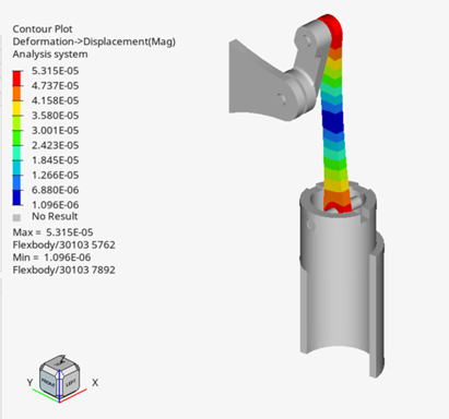
Note: The displacement contour is shown with respect to the instantaneous CG of the flexbody. -
From the Animation Toolbar, click the Play button
 to review the
animation of deformation variation during the simulation.
- From the Contour panel, select Stress (t) from the drop-down menu for Result type.
-
Click Apply to
display the contour plot.
Figure 14. 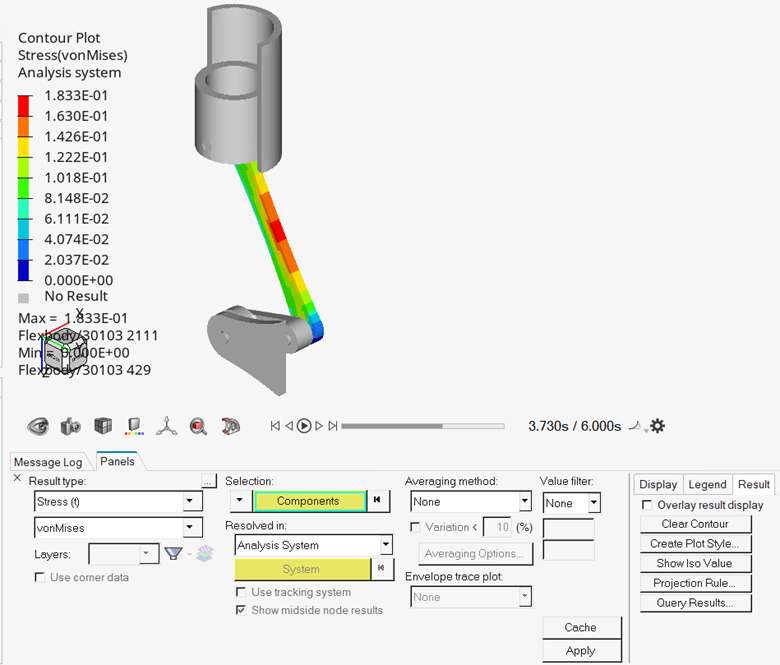
- From the menu bar, select and name the session file mv_flexbody_sess.mvw.