Sequential Simulation: Extension - Retraction Analysis of a Landing Gear
Tutorial Level: Intermediate In this tutorial, you will learn how to add a graphic by importing geometry using HyperMesh and create a sequential simulation script to simulate the extension and retraction of a landing gear.
- Sequential Simulation
-
Often, the total dynamic behavior of a multibody model needs to be captured through more than one solution sequence. Typical examples of such conditions include:
- The model configuration changes after a certain amount of time.
- One type of analysis has to occur before the other. For example, a static solution is required before a dynamic run.
- Complex models may not solve with a single solver setting. The solver settings may need to be changed for a certain period in the overall simulation time.
Such conditions may be simulated by providing a set of commands to the solver that achieves the above type of sequences. Such simulations are referred to as sequential simulations. Generally, the solver receives more than one solution (simulate) command. You'll learn to script such a simulation sequence through this exercise.
- Exercise
-
In this exercise, a landing gear mechanism is simulated for its extension and retraction. A sequence of simulations need to be scripted such that the mechanism is retracted within a certain period of time at the end of which the simulation is halted, the model configuration is changed for retraction and the solution is executed again for extension.
Figure 1. Main Landing Gear of an Aircraft 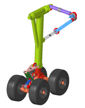
Before you begin, copy the file(s) used in this tutorial to your working directory.
Phase 1
In this phase, you will prepare the landing gear model to simulate the retraction of the landing gear.
Open the Landing Gear Mechanism
In this step, you will open a landing gear model and attach a graphic for the aircraft body.
-
From the toolbar, click Open Model
 .
.
Or
Open model by selecting .
-
From the Open model dialog, select the file
MainLandingGear.mdl and click
Open.
The loaded model will look as shown below. Review the model for its bodies and joints.
The model consists of linkages of the cylinder and piston that hold the wheel as well as linkages for the extension and retraction of the whole landing gear unit within the aircraft body. The model also contains a body defined for aircraft but without graphics. As a first step, you will add a graphic for the aircraft body part for visual representation.
Figure 2. Main Landing Gear Mechanism 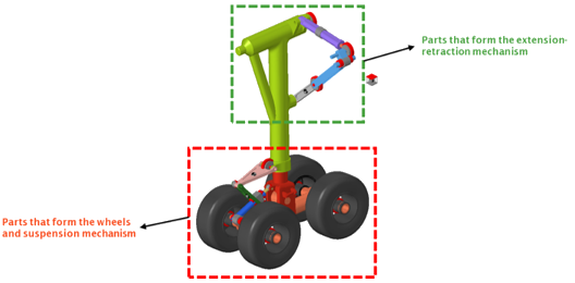
- From the File menu, select the .
- Select the option Import CAD or Finite Element Model Only. With this selection, only the graphics will be imported without creating any bodies.
- For Input File, select HyperMesh.
-
Click Input File
 and select
Aircraft_Structure.hm as the input file.
and select
Aircraft_Structure.hm as the input file.
- Click OK.
-
The H3D file is generated and the graphic is imported.
Figure 3. The Model after Importing a Graphic for the Aircraft Body 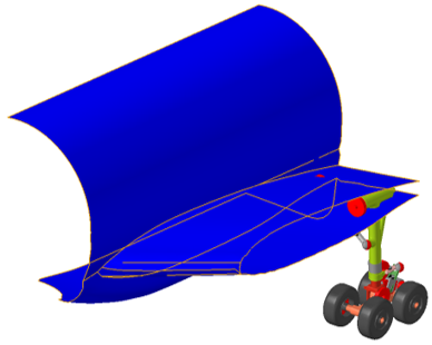
-
From the modeling window, go to the Graphics and select
the just-added graphic g_Aircraft_Structure_graphic.
The Entity Editor for the aircraft structure graphic is displayed.Note: If the Entity Editor is not visible, right-click on the entity in the browser and click Show Properties.
-
In the General section:
-
Click on the Aircraft 5 Body icon in the
modeling window.
Or
Click on the ellipsis
 to display the Advanced selection
dialog. Select Aircraft 5 and click
OK.
to display the Advanced selection
dialog. Select Aircraft 5 and click
OK.Figure 4. Aircraft Structure Graphic Entity Editor 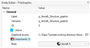
-
Click on the Aircraft 5 Body icon in the
modeling window.
Define a Motion to Retract the Landing Gear
This step involves defining the motion required for retracting the landing gear.
-
From the Model ribbon, in the
Entities group click on
Motions
 to invoke the motions guide bar.
-
Resolve the Joint collector to the Cylindrical Joint
ActPis_ActCyl_Cyl (shown in the image below), which
is defined between the bodies Activating Cylinder and Activating Piston.
Figure 5. Cylindrical Joint - ActPis_ActCyl_Cyl 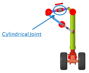
Figure 6. Joint guide bar 
-
Click on Create
 .
.
-
Exit the guide bar by clicking on
Cancel
 .
.
-
In the Entity Editor - General section, specify
Label as
Retraction Motionand Varname asmot_ret. -
In the Properties section, select Type as Expression. In
the Expression field, enter the expression
`STEP(TIME,0,0,5,-750)`.Note: The above STEP expression ramps the value of motion from 0 at 0 seconds to -750 at 5 seconds.The expression is enclosed within` `called backtics. This key is generally found on the top left corner of the keyboard below the Esc (Escape key). The backtic is not the same as‘ ‘(apostrophe, next to the semicolon).Figure 7. Retraction Motion 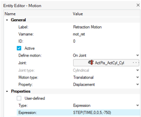
-
Similarly, add another motion and name it
Aligning_Motion. Resolve the Joint collector to the Cylindrical Joint LnkCyl_LnkPis_Cyl defined between the MLG Cyl and MLG Pis bodies (see the image below).Figure 8. Cylindrical Joint - LnkCyl_LnkPis_Cyl 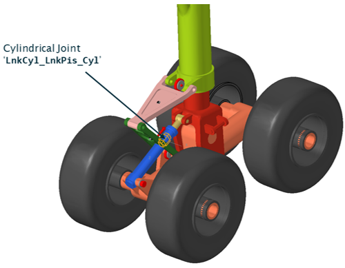
-
From the Properties section of the Entity Editor,
select Type as Expression. In the Expression field, enter
the expression
`STEP(TIME,0,0,2,-100)`.Figure 9. Aligning Motion Entity Editor 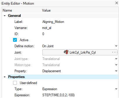
- Save your model as landinggear_motion.mdl.
Run a Dynamic Analysis to Simulate the Retraction of the Main Landing Gear
This step involves running a transient analysis of the main landing gear mechanism.
- From the Model Browser, select Default Analysis.
-
From the Entity Editor, set the End
time to
5seconds. -
From Analyze Ribbon, open the Run Motion
Analysis dialog by clicking the satellite icon
 for Analysis Settings.
-
Enter the Run name as
lg_retractand specify the Output Directory. -
Click Run to initiate the live simulation.
Observe the model animate as the run progresses.
- Once the simulation is complete, close the Run Status window.
-
Exit the Review context by clicking on the Review run
results icon
 in
the Run tool set.
in
the Run tool set.
Phase 2
In Phase 2, write a Templex template to script and run a sequential simulation to simulate the retraction and extension of the landing gear mechanism.
- Perform math and string operations
- Add solver statements un-supported by MotionView interface
Define an Extension Motion for the Landing Gear
This step involves defining the extension motion of the landing gear.
-
From the Model ribbon, click
Motions
.
-
Add another motion with Label as
Extension
                        Motion
and Variable Name asmot_ext. Resolve the motion to the same joint for which the Retraction Motion has been defined. -
From the Properties section of the Entity Editor, set
the type of motion as Expression and enter the following
in the Expression field:
`STEP(TIME,5,-750,10,0)`. Click to finish editing.
Figure 10. Extension Motion Entity Editor 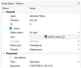
Define a Template to Run the Sequential Simulation
In this step, write a template to script a sequential simulation.
-
From the Analyze ribbon, click on
Templates
 in the Solution group.
-
On the guide bar, click to generate the Template.
- Locate the Template in the Model Browser, under Templates, and select it.
- In the Entity Editor, specify a Label and Varname.
- For Type, select Write text to solver command file.
-
Click on Edit Template to open the template window.
Select the Edit option, located in the top right corner,
and enter the script given below.
Note:
The entries in the curly braces {}, refer to the idstring of either Extension Motion or Retraction Motion. This idstring attribute can also be accessed using the Expression builder,
 .
.The following commands are MotionSolve command statements in the XML format. Since the solver refers to entities through their ID numbers, the element_id value is resolved to the motion IDs. If you have used different varnames for the motions than mentioned below, the text could differ.
<!--Deactivate the extension motion first -->
<Deactivate
element_type = "MOTION"
element_id   = "{MODEL.mot_ext.idstring}"
/>
<!--Simulate for 5 seconds -->
<Simulate
analysis_type       = "Transient"
end_time            = "5.0"
print_interval      = "0.01"
/>
<!--Deactivate the retraction motion -->
<Deactivate
element_type = "MOTION"
element_id   = "{MODEL.mot_ret.idstring}"
/>
<!--Activate the extension motion that was deactivated during the first simulation -->
<Activate
element_type = "MOTION"
element_id   = "{MODEL.mot_ext.idstring}"
/>
<!--Simulate for 5 more seconds -->
<Simulate
analysis_type       = "Transient"
end_time            = "10.0"
print_interval      = "0.01"
/>
<STOP/>

<!-- Stop the simulation. Any further commands below this command will not be executed -->
The above script has five blocks.- Block 1
- Deactivates the motion which defines the extension of the landing gear.
- Block 2
- Simulates the model for the retraction of the landing gear.
- Block 3
- Deactivates the motion used to retract the landing gear.
- Block 4
- Activates the motion which defines the extension of the landing gear.
- Block 5
- Simulates the model for the extension of the landing gear.
The Stop command is used to stop the simulation at the time set in the last Simulate block.
Note: A template can be used either to add modeling entities to the solver deck, such as joints, markers, and so on, that may not be supported by MotionView, or command entities such as simulation parameters, activation and deactivation, and so on. The MotionSolve XML is divided into two sections.- Model Section
- All model elements are defined. To write to this section from the template, for Type select Write text to Solver input deck.
- Command Section
- Commands for the solver simulation are defined. To write to this section from the template, for Type select Write text to Solver command file.
Create Output Requests and Rerun the Model
This step involves creating output requests and re-running the model to measure the Angular Displacement and Angular Velocity of the landing gear.
-
From the Analyze ribbon, click on
Outputs
 .
.
-
Create an output request. From the Outputs guide bar:
- Set Type to Displacement, Entity, and Joint.
-
Click the ellipsis next to Joint to open the Select a Joint
dialog.
- For the Joint collector, select the Revolute joint between the Main LG Cylinder and Aircraft-5, MLG_Ac_Rev.
-
Provide a Label as
Angular Displacement of Landing
                                Geat
and Variable Name aso_ang_disp.
- Similarly, create another output request to measure the velocity at the same joint as above.
Simulate and Animate the Model
This step involves running the model to simulate the retraction and extension of the main landing gear model and animating it.
- Click on Default Analysis in the Model Browser and specify End Time as
10seconds. - From the Run Motion Analysis dialog, specify the Run name
as MLG_Simulation and the Output
directory. Click Run.
Figure 11. Run Analysis 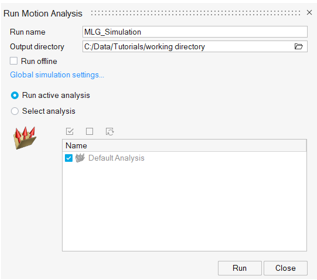
- Once the solution is complete, click Plot on the Run Status dialog, to launch HyperGraph. The Create Curves by File dialog is automatically displayed.
- Select Marker Displacement > REQ/70000000 MLG_Ac_Rev on Main LG
Cylinder(Angular Displacement of Landing Gear) > YAW for
Y Source.
Figure 12. Plot Angular Displacement of Landing Gear 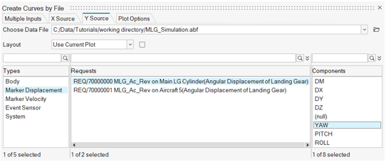
Figure 13. Angular Displacement of Landing Gear Plot 
- From the top right corner, click Add a Page to open a new
page in HyperGraph.
Figure 14. Add a New Page 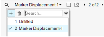
- Click Open Plot
 .
. - Select Marker Velocity > REQ/70000002 MLG_Ac_Rev on Main LG
Cylinder(Angular Velocity of Landing Gear) > WX for Y
Source.
Figure 15. Angular Velocity of Landing Gear Plot 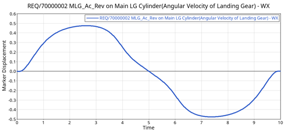
- Save your model and exit the session.