Co-Simulation with Twin Activate via Function Mockup Interface (FMI)
Tutorial Level: Advanced In this tutorial, you will learn about the process of setting up an MBS model to co-simulate with Altair Twin Activate by following the FMI.
The co-simulation “flavor” of the FMI prescribes a protocol for different software to iteratively communicate data with one another, thus enabling multiple solvers to co-simulate amongst one another.
By leveraging this interface, MotionSolve can co-simulate with Twin Activate, or with any other software that supports the FMI standard. To do this, the MotionSolve model is first converted to a Functional Mockup Unit (FMU) which is a stand-alone modeling unit that represents the MotionSolve model. FMUs adhere to the protocol prescribed by the FMI and can thus be imported or exported by software that support this interface.
MotionSolve can export an FMU of type “co-simulation” which can be imported into other software such as 1-D simulators. The type “co-simulation” implies that the MotionSolve FMU is responsible for calculating its part of the solution, that is, MotionSolve is invoked at the time co-simulation is started.
This tutorial will describe the steps required to:
- Open and inspect the MBS model.
- Export an FMU from MotionView with exposable parameters.
- Use the FMU to modify the model through exposable parameters and run a co-simulation analysis using Twin Activate.
- Review co-simulation results in Twin Activate.
A model representing a quad-rotorcraft is used for this tutorial. The model structure, rotor blades, and so on, are modeled using MotionView/MotionSolve and Twin Activate is used to control the spin rate of the rotors to control the thrust and lateral movement of the rotor. Roll forces are applied to the rotorcraft to mimic the effect of wind. The aim of the simulation is to control the thrust to make the rotor achieve a target height.
- Files Required
-
Before you begin, copy the file(s) used in this tutorial to your working directory.
Review the Model
- Launch a new session of MotionView.
-
From the toolbar, click the Open Model
 icon.
Tip: You can also select .
icon.
Tip: You can also select . - From the Open model dialog, select the Quadrotor_complete.mdl file from your <working directory> and click Open.
-
Review the model.
-
Observe the model's Inputs and Outputs.
Figure 1. Quadrotor Model 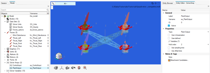
Note: The model has been instrumented to contain inputs (ControlInput) and outputs (PlantOutput). Outputs are signals sent by MotionSolve to the environment (Twin Activate). Inputs are signals accepted by MotionSolve from the environment.In this example, the following Outputs are computed by MotionSolve and passed to the external solver (Twin Activate):Name Description Roll Angle The roll angle of the rotor craft in the global frame. Altitude The height of the rotor craft in the global frame. Pitch Angle The pitch angle of the rotor craft in the global frame. PosX The X coordinate of the rotor craft in the global frame. PosY The Y coordinate of the rotor craft in the global frame. VX The X velocity of the rotor craft in the global frame. VY The X velocity of the rotor craft in the global frame. The following Inputs are expected from the external solver by MotionSolve:Name Description Roll_Command The control signal for controlling the roll of rotor craft. Throttle_Command The control signal for controlling the throttle of rotor craft. Pitch_Command The control signal for controlling the pitch of rotor craft. -
Observe the two Wind Disturbance forces, in the
Forces folder, which are deactivated by
default.
Figure 2. Wind Disturbance Force's Properties 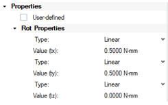
-
In the Data Sets folder, locate the
Forces_options data set and click on it to
view its Entity Editor.
Figure 3. Forces_options Data Set 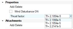
- Wind Disturbance ON: A Boolean data set variable (True/False), which is linked to the Wind Disturbance force. By default, the Wind Disturbance ON Boolean variable is deactivated. Checking the box, results in activating the corresponding force.
- Thrust Factor: An Option data set variable, meant to provide three different choices for the Rotors’ Thrust factor values. It is used for the calculation of the Rotors’ thrust forces.
-
Observe the model's Inputs and Outputs.
Export MDL as FMU
-
From the menu bar, click to invoke the FMU Editor dialog.
Figure 4. Export Model as FMU 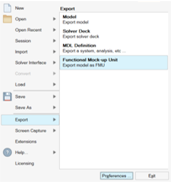
-
Review the Inputs and Outputs
Channels from the respective tabs.
Note: Parameters help in varying the FMU system configuration for the simulation. This enables FMU to be designable through a finite set of parameters.
- Click on the Parameters tab.
- Expand the Model Tree by clicking on the plus icon +.
-
Expand the Vehicle body and select the
mass property.
Figure 5. Enable Vehicle's Body's Mass Property 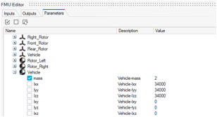
-
Expand the Forces_activator data set and select all
available options.
Figure 6. Enable Data Set's Parameters 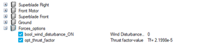
-
Click on the Save icon
 for Select FMU File and
specify the name for the FMU as
for Select FMU File and
specify the name for the FMU as Quadrotor.fmu.Figure 7. Use FMU Editor to Save the Model 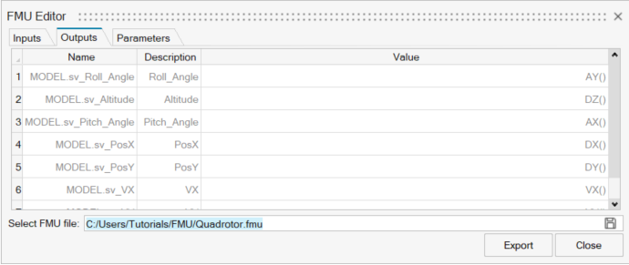
-
Click the Export button.
Note: You may be prompted to save your model before it is exported, click Yes.MotionView creates an archive (or zip) package (of type *.fmu) that contains the complete MotionView model and other libraries as per the FMI standard. Once the export is complete, an FMU is created in your working directory. Since an FMU is basically a ZIP file, you can open this file to inspect its contents. A MotionSolve FMU consists of the following sets of files:
- modelDescription.xml
- This file describes the FMU and its contents to the importing software (here Twin Activate).
- "binaries" folder
- This folder contains platform specific binaries that are required to use this FMU for co-simulation with MotionSolve.
- "resources" folder
- This folder contains the archived MDL model along with all the files that are required to run the model. Also, it contains some auxiliary files that are required to run co-simulation.
Import the FMU in Twin Activate
-
Before the FMU is imported into Twin Activate, set the
following environment variables that indicate the install location of HyperWorks. The environment variables differ based on the
operating system:
Operating System Environment Variable/s Windows ALTAIR_FMU_ROOT=altair_install Linux ALTAIR_FMU_ROOT=altair_install LD_LIBRARY_PATH= altair_install/altair/hwsolvers/motionsolve/bin/linux64:$LD_LIBRARY_PATH
(MotionSolve solver location is being appended to the LD_LIBRARY_PATH environment variable)
RADFLEX_PATH= altair_install/altair/hwsolvers/common/bin/linux64
Note: altair_install is the folder where Altair HyperWorks is installed. -
Once the setup is finished, open the
Quadrotor_Control_fmu.scm file from your
<working directory> using the Open
Model button.
Tip: You an also use the menu option to select the Quadrotor_Control_fmu.scm file.
Figure 8. Quadrotor Control Diagram inTwin Activate 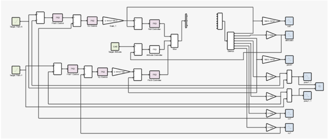
-
From the Palette Browser on the right, double-click Twin Activate > CoSimulation and drag-drop the
FMI block into the model GUI.
Figure 9. FMI Block 
Note: If the Palette Browser is not visible on the right, you can turn it ON by clicking in the Menu. -
Double-click on the FMI block to specify the FMU.
Figure 10. Load the FMU within the FMI Model 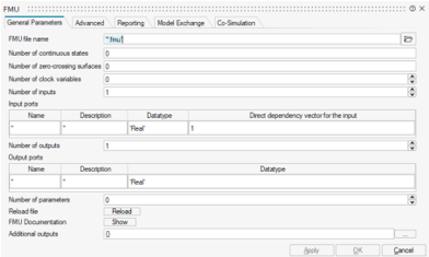
-
Click the browse file button
 and select the FMU exported from MotionView.
Note: Once the FMU is loaded, you will notice that several of the other fields in this dialog are auto-populated.
and select the FMU exported from MotionView.
Note: Once the FMU is loaded, you will notice that several of the other fields in this dialog are auto-populated.Figure 11. Model's Inputs and Outputs are Auto-populated 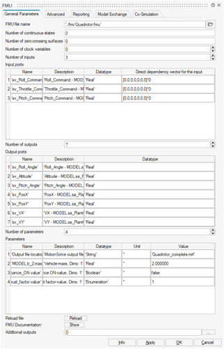
Note: Model properties that were enabled during FMU export in MotionView, can be modified from the Parameters menu.Tip: You can specify the different location of the output files from MotionSolve (.mrf, .abf, .h3d, and so on) by changing the text in the parameter with the name “Output file location”. -
The Parameters section contains model’s parameters that were made visible
during FMU export in MotionView. From here, you
can:
- Alter the Vehicle body’s mass.
- Activate/Deactivate the Wind Disturbance ON Boolean variable.
- Select between different values of Thrust Factors.
- Make sure the 3rd and 4th parameters are set to false and 1 respectively.
- The Info button on the dialog box provides information about the FMU being imported. Click the same to review the details and click Close to exit.
-
Click OK to select the FMU and exit.
The FMI block is changed to reflect the right number of inputs and outputs based on the FMU.
Figure 12. FMI Block After Loading the FMU Model 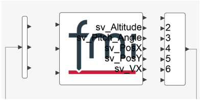
Tip: You can resize the FMI block until the input and output names become visible.Figure 13. Resize FMI Block 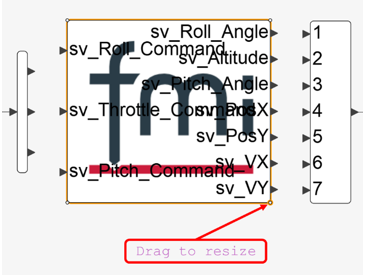
-
Connect the FMI block to the rest of the model through connector ports.
After connection, your model should look like the one shown below.
Figure 14. Connect FMI Block to the Twin Activate Model 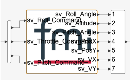
Figure 15. Twin Activate Final Diagram 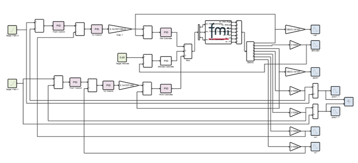
Run the Twin Activate Model
-
Click .
Note: Twin Activate needs to be aware of the location of the MotionSolve licensing utility in order for the run to complete successfully. The Preferences dialog allows this to be set.
-
Under the Twin Activate category,
select Paths. Make sure that all options under
Cosimulation with MotionSolve are cleared.
Figure 16. Set Up Paths Preferences 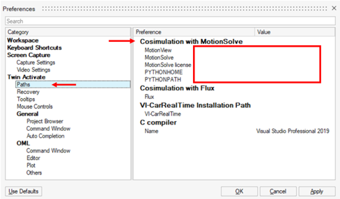
-
Click the Run button
 to begin the co-simulation.
Note: Twin Activate invokes the FMU which in turn generates an XML from the packaged MDL and uses that to begin the co-simulation. The co-simulation is based on inter-process communication (IPC), thus MotionSolve is started on a new thread.
to begin the co-simulation.
Note: Twin Activate invokes the FMU which in turn generates an XML from the packaged MDL and uses that to begin the co-simulation. The co-simulation is based on inter-process communication (IPC), thus MotionSolve is started on a new thread.
Review the Results
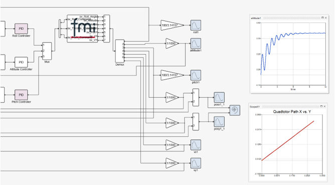
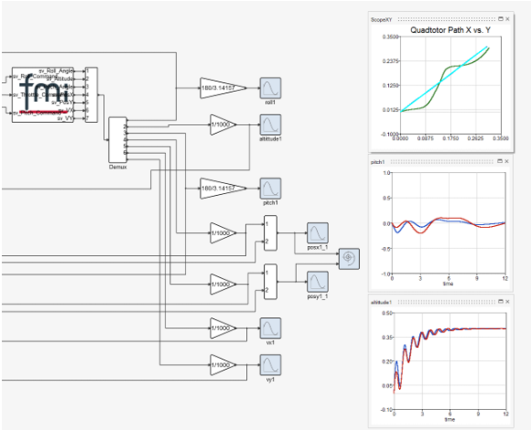
The altittude1 scope shows the altitude of the rotor craft. After about 8 seconds, the quadrotor seems to stabilize at the desired height.
The ScopeXY scope shows the target X, Y path (red) versus the actual X, Y path (pink) of the quadrotor. You can observe that the actual and the target path coincide, in the absence of an external disturbance.
You can retrieve results from the MotionSolve output files like the MRF, ABF, PLT, H3D, and so on. You may also create expressions in your MotionSolve model that are used solely to monitor the system.
Modify the Model's Parameters and Review the Results
- Double-click to open the FMU block.
-
In the Parameters section:
-
Change the vehicle's mass value to
2.5. -
Enable the Wind Disturbance ON parameter by
entering
true. -
Pick a different Thrust factor by entering the
value
2.
Note: The Thrust factor’s value options correspond to the Integer value in the Modifying existing user data entry dialog in MotionView. To access this dialog, click on the Forces_options data set and follow the steps shown in the figure below.Figure 18. Access Modifying Existing User Data Entry Dialog 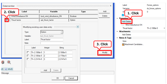
Figure 19. FMU Parameter Modifications 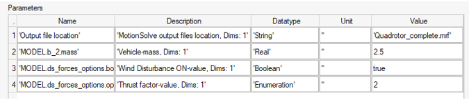
-
Change the vehicle's mass value to
- Click OK to apply the changes.
-
Click to initiate the co-simulation.
The new results will overlay the existing results.
-
Review the results.
Figure 20. Results Plotted on Top of Old Results