Rigids
Rigid elements are created in a space between two nodes of a model where a rigid connection is desired.
An option to calculate independent node is available.
Rigid elements are element config 5 and are displayed as a line between two nodes with the letter R written at the centroid of the element.
 |
 |
Rigid link elements are element config 55 and are displayed as lines between the independent node and the dependent node(s) with RL displayed at the independent node of the element.
Create Rigid Elements
Use the Rigids tool to create rigid or rigid link elements.
-
From the Model ribbon, select
the Rigids too.
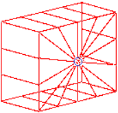
Figure 3. 
-
Define the element.
Option Action Type Select a rigid element type. Linear 1D Create one-dimensional elements based on a projection of Elems A to Elems B. Elems A Select the elements where you want the elements to begin. Restriction: Only available when the Linear 1D check box is selected.Elems B Select the elements where you want the elements to end. Restriction: Only available when the Linear 1D check box is selected.Density A-B Specify the number of plot elements you want created between each of the selected elements. Restriction: Only available when the Linear 1D check box is selected.Calculate independent node The independent node is calculated to be at the centroid of previously selected dependent nodes. So independent node selection is made unavailable. Independent node Select the independent node of the rigid element. Dependent node(s) Select one or more dependent nodes. Dependent DOF Select degrees of freedom at dependent nodes. - Click Create.
Update Rigid Elements
Use the Entity Editor to update rigid elements.
Combine Rigid Elements
- From the Model ribbon, click the arrow next to the Interactions tool group and select Combine Rigids.
-
Define parameters.
Option Action Elements Select the rigid elements that you wish to combine. The rigids and rigidlinks must have the same independent node and DOFs. If any combined rigid link elements have dependent nodes attached as a set, the resulting rigid link will also have dependent nodes attached as a set. This set is created for a result element. The nodes sets attached to combined elements are deleted after combining.
Combine Rigid With: Choose between common independent node and any common node. - Click Combine.