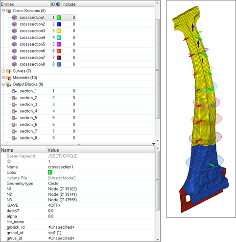
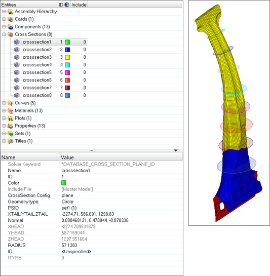
Cross Sections
Cross section entities store cross section definitions used in a crash analysis.
A cross section is defined by a set of nodes and elements. These sets can be explicitly defined in the entity or computed by intersecting a given geometry (plane, circle) with a set of elements or components.
Supported Solver Cards
Solver cards supported for cross sections.
LS-DYNA Cards
| Card | Description |
|---|---|
| *DATABASE_CROSS_SECTION_PLANE(ID) | XsectionPlane |
| *DATABASE_CROSS_SECTION_SET(ID) | Define a cross section for resultant forces written to an ASCII file SECFORC. |
PAM-CRASH 2G
| Card | Description |
|---|---|
| SECFO / | |
| SECFO / NTYP = PLANE |
Transmission force at cutting plane Graphics available. |
| SECFO / NTYP = CONTACT |
Cumulated contact forces No graphics available. |
| SECFO / NTYP = LINK |
Cumulated link forces No graphics available. |
| SECFO / NTYP = SECTION |
Transmission force at section No graphics available. |
| SECFO / NTYP = SUPPORT |
Support reaction force No graphics available. |
| SECFO / NTYP = VOLFRAC |
Fraction of volume affected by a defined criterion No graphics available. |
| SECFO / NTYP = CONT_MS |
Contact forces between Main and Secondary nodal groups No graphics available. |
| SECFO / NTYP = DETECT |
Accumulated nodal mass in selected volume No graphics available. |
| SECFO / NTYPE = TIED_MS |
Tied forces between main and secondary nodal groups (v2018) |
Radioss Cards
| Card | Description |
|---|---|
| /SECT | A section is a set of nodes and a set of
elements. Note: Block Format
Keyword |
| /SECT/CIRCLE | A section is a set of nodes and a set of elements.
Sets are built automatically, by intersecting the concerned groups of elements with
a disc. Note: Block Format
Keyword |
| /SECT/PARAL | A section is a set of nodes and a set of elements.
Sets are built automatically, by intersecting the concerned groups of elements with
a parallelogram. Note: Block Format
Keyword |
Create Cross Sections
Create cross sections using the Cross Section Assistant.
-
In the Model Browser, right-click and select from the context menu.
The Cross Section Assistant dialog opens.
-
In the Cross Section Name field, enter a name for the cross section.
Note: If Create Multiple is enabled, the cross section name defines the prefix of each cross section created.
- In the Cross Section Type field, select the type of cross section to create.
- In the Entity Selection field, use the entity selector to select the mesh that will be cut by the cross section.
-
Select the Create Multiple checkbox to create multiple
cross sections simultaneously.
Note: When this checkbox is enabled, a cross section path definition will replace the Base Node and Normal Definition parameters.
- If you are creating multiple cross sections, in the Cross Section Path field, use the entity selector to select a node path for the creation of each cross section.
-
If you are creating a single cross section:
- Click Create.
 |
 |