This realization realizes t-welds, lap-welds, laser-welds, and
butt-welds.
Restriction: Available in Abaqus, LS-DYNA, Nastran, OptiStruct, and Radioss.
This weld type is identified automatically based on the orientation of the links to
each other.
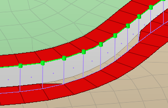
The dimensions and properties assigned to all heat affected zones (HAZ) can be
defined separately. Normal directions of quad weld elements and HAZ elements can be
controlled. An edge treatment can be defined for t-welds and butt-welds to move the
edge a precise distance from the opposite link. Figure 1. Seam Quad
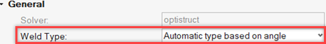
General Info
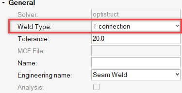
Weld Type
Defines weather to setup a configuration exclusively for a T, L, or B
connection, or automatically setup a configuration for each connection
based on the angle.
The connection type is dependent on the:
B/L classification angle
L/T classification angle
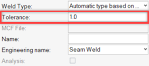
Tolerance
Defines the distance from the connector location.
Only entities within this tolerance can be taken into account for the
final realization. The tolerance is used to verify whether adequate link
candidates are available to be connected with respect to the number of
layers.
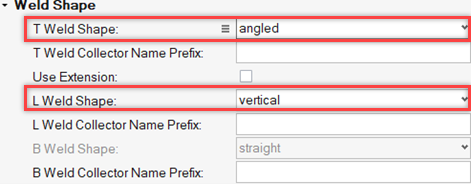
Weld Shape
T Weld Shape
Defines how the T weld is created.
Figure 2. Vertical
Figure 3. Vertical and angled
Figure 4. Angled (double)
Figure 5. Vertical (edge) and angled (double)
Figure 6. Angled
Figure 7. Vertical (edge) and angled (horizontal)
Figure 8. Vertical and angled (doubled)
Use Extension
Interpolate an extension of the T joint and calculate the weld
dimensions from this location.
Figure 9. Use Extension Interpolation
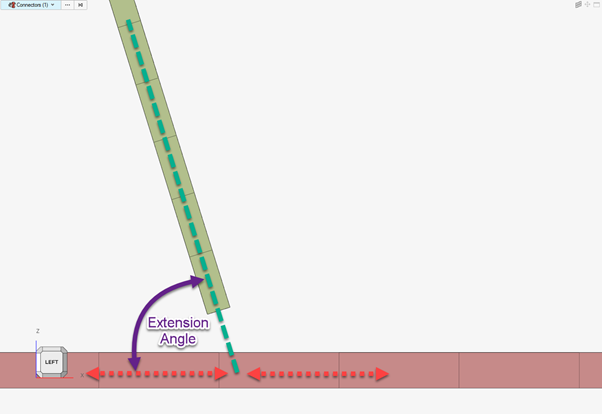
Extension Angle
If the Links are at an angle greater than the “Extension Angle” then the
“Use Extension” operation is used.
L Weld Shape
Defines how the L weld is created.
Figure 10. Angled
Figure 11. Vertical and angled
Figure 12. Vertical
B Weld Shape
B welds are always created straight.
Figure 13. Straight
With Caps
When enabled, seams are closed with a tria element.
This option allows the realization to use Trias in the weld and HAZ.
This can improve element quality on connectors with a very tight
radius.
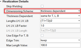
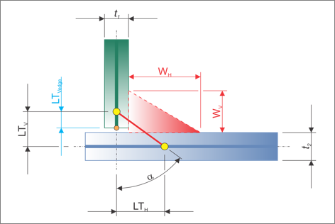
Realization Details
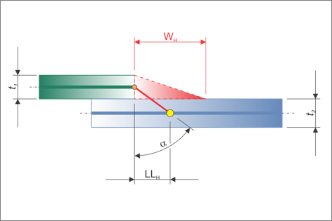
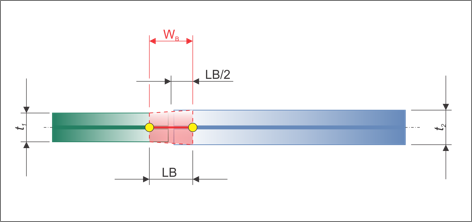
The Realization Details settings position the yellow marked nodes in the following
figures. The dimensions of the welds are dependent on the Weld Shape
settings.
Figure 16. T Dimensions
Figure 17. L Dimensions
Figure 18. B Dimensions
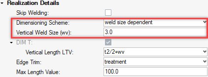
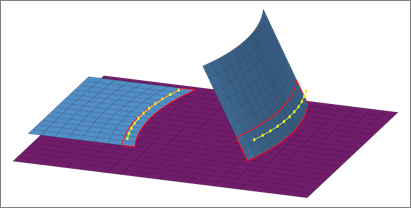
Dimensioning Scheme
Defines the dimensioning scheme for the dimensions of the T weld, L
weld, and B weld connections.
user input
Manually define discrete values for the weld dimensions,
shown in black in Figure 16, Figure 17, and Figure 18. The horizontal dimensions can be
defined using a length or an angle.
thickness dependent
Choose a formula to define the weld dimensions, shown in
black in Figure 16, Figure 17, and Figure 18. The provided formulas are all dependent
on the thicknesses t1 and t2. A formula can be chosen
individually for each verticalV and horizontalH distance, or
the same formula can be used for T, L and B.
weldsize dependent
Manually define discrete values for the weld dimensions,
shown in red in the Figure 16, Figure 17, and Figure 18. The verticalV and horizontalH distances
are defined with formulas reflecting the weld sizes and the
t1 and t2 thicknesses.
DIM T (Dimensioning T)
Input
Thickness dependent
Weldsize dependent
Horizontal Lengths LTH
by angle
by length
Pitch Size
T1
T2
(T1+T2)
(T1+T2)/2
T Minimum
T Maximum
Lh, LB, LV Factor*
t1/2+wh/2
t1/2+wh
wh
Vertical Length LTV
by length
by edge
By Edge
Pitch Size
T1
T2
(T1+T2)
(T1+T2)/2
T Minimum
T Maximum
By edge + 0.4*T1
Lh, LB, LV Factor*
t2/2+wv/2
by edge
t2/2+wv
wv
DIM L (Dimensioning L)
Input
Thickness dependent
Weldsize dependent
Horizontal Lengths LTH
by length
by angle
Pitch Size
T1
T2
(T1+T2)
(T1+T2)/2
T Minimum
T Maximum
Lh, LB, LV Factor*
wh/2
DIM B (Dimensioning B)
Input
Thickness dependent
Weldsize dependent
Lengths LB
by length
by angle
Pitch Size
T1
T2
(T1+T2)
(T1+T2)/2
T Minimum
T Maximum
Lh, LB, LV Factor*
wb
by edges
*LH, LB, LV Factor: Is a calculation factor that can be added to the
calculation. The default value is 1.0, so the length calculation
selection remains unchanged.
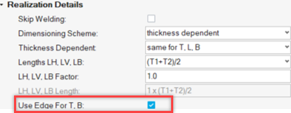
Use Edge to T, B
If the weld is classified as a T or a B weld, the weld is created from
the edge. You do not need to put any values in for Vertical Length for T
welds and Width for B welds.
Edge Treatment
Treatment
Try to move the edges of the mesh to meet the dimension
scheme. Edge treatment is not needed when the different
length dimension settings are set to by edge. When enabled,
edges are allowed to move.
Keep
Keep the mesh if the weld is realizing above the edge.
Cut
Trim the mesh below the weld if the weld is realizing above
the edge.
Max Length Value
Defines the maximum length value.
This setting is useful when lengths are calculated based on thicknesses.
If a length is greater than the Max Length Value, then the Max Length
Value will be used instead.
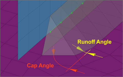
Caps
Determines how caps are created.Figure 19. Cap Angle and Runoff Angle
Figure 20. Sharp Corner Enabled
Figure 21. Sharp Corner Disabled
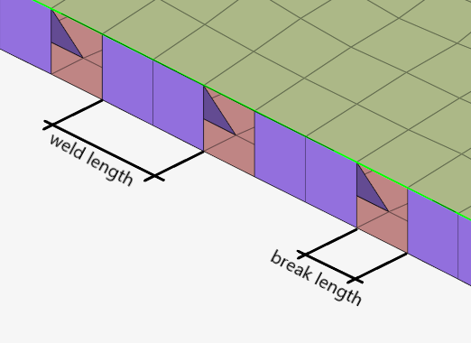
Skip Welding
Allows welds to be realized periodically by creating breaks between the
weld elements along the connector’s length.
Note: If Pitch is set to
Retain Nodes, this option is not
available.
Weld Option
Length
Define the length before the next break.
Scale (elem)
Define the scale of element before the next
break.
Break Option
Length
Define the Break in terms of length.
Scale (elem)
Define the break in terms of scale on
elements.
Allow Weld longer than (%)
Upper bound tolerance allowed by weld length.
Allow Weld shorter than (%)
Lower bound tolerance allowed by weld length.
Figure 22. Skip Welding ON, Definition of Weld Length and Break
Length
Element Details
The Element Details settings control the normal directions of the weld, as well as
the HAZ elements.
Vertical Element Normal, Angled Element Normal, and HAZ Element Normal can be set to either:
Towards welder
The element normals are in the direction of the weld.
Away from welder
The element normals are in the opposite direction of the weld.
Figure 23. Towards welder Figure 24. Away from welder
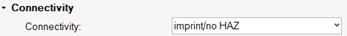
Connectivity Info
The following options give you the ability to change how the realization connects to
the mesh.
imprint (default)
Creates quad weld elements and stitches them to both links by adjusting
their mesh. The HAZ is created in this option.
skip imprint
Creates quad weld elements but does not change the meshes of the links.
Instead, additional elements are created to represent the requested HAZ.
These elements are organized in the ^conn_imprint component and can
later be used for a manual imprint after they have been manipulated to
your needs. This option is helpful when working with more complex areas,
where the standard imprint functionality fails, for example, conflicting
connectors.
imprint/no HAZ
Creates quad weld elements and stitches them to both links by adjusting
their mesh. Mesh modifications are as minimal as possible and no HAZ are
performed.
none
Creates quad weld elements only. Quad weld elements will not be attached
to the links. The connection will need further attention.
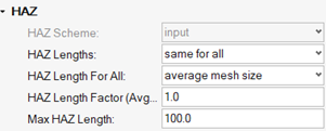
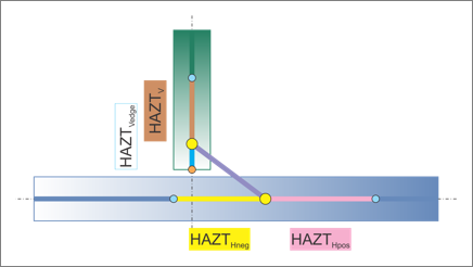
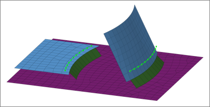
HAZ Info
The HAZ Info settings define the lengths of the different heat affected zones (HAZ),
which are dependent on the HAZ lengths for T, L and B (defined in Realization Details). The
HAZ length settings vary depending on the defined weld shapes (vertical, angled,
vertical and angled, caps).
Rule-based realization:
First try to realize with user-specified HAZ lengths.
If step 1 fails, realize with reduced HAZ lengths/reduced HAZ’s elements
length at certain position on connectors.
If step 2 also fails, realize with no HAZ’s.
HAZ Scheme
Choose a dimensioning scheme for the HAZ lengths of T, L, and B.
input
Enables you to decide if the HAZ lengths should be defined
individually, or if all HAZ lengths are determined using the
same approach (same as all).
weldsize dependent
Only available if weldsize dependent has been chosen for the
Dimensioning Scheme as well.
HAZ Lengths
same as all
Assigns the same length to all HAZ lengths.
individual
Assign HAZ lengths individually.
HAZ Lengths (various)
The following options are available in the various
HAZ length settings.
input
Requires a discrete value be specified for the length.
average meshsize
Length is dependent on the average mesh size in the local
area where the imprint is performed.
by thickness
Sets the length to the same value as the thickness of the
link getting the HAZ.
LTH
Horizontal length for T connections, which is the length
between the foot points of the vertical and angled part of a
seam.
LLH
Horizontal length for L connections, which is the length
between the foot points of the vertical and angled part of a
seam.
LB
Butt weld length.
skip HAZ
Skips individual HAZ that are not required.
same as positive side
Assigns the same length as the positive side to the negative
side.
wh or wh/2
Length is dependent on the horizontal weld size. Only
available when HAZ Scheme is set to weldsize dependent.
wv or wv/2
Length is dependent on the vertical weld size. Only
available when HAZ Scheme is set to weldsize dependent.
wb or wb/2
Length is dependent on the butt weld size. Only available
when HAZ Scheme is set to weldsize dependent.
LTVedge
Choose between skip HAZ and LTVedge. Only available for
the HAZTvedge length.
HAZ Length Factor (Avg. Meshsize/Thickness)
Factor that increases or decreases the HAZ lengths, which have been
defined using the average meshsize or by thickness length options.
Max HAZ Length
Maximum length for all HAZ lengths. If the HAZ length is greater than
this value, then the Max HAZ Length is used.
Dimensioning and Heat Affected Zones (HAZ):
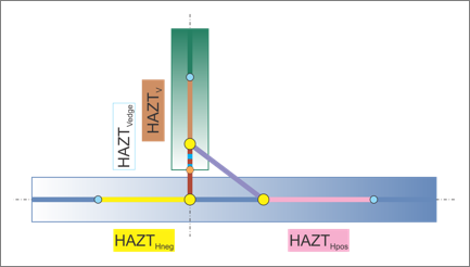
Dimensioning T
Figure 25. Dimensioning T
Figure 26. Vertical T Weld HAZ
Figure 27. Angled T Weld HAZ
Figure 28. Vertical and Angled T Weld HAZ
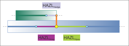
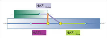
Dimensioning L
Figure 29. Dimensioning L
Figure 30. Vertical L Weld HAZ
Figure 31. Angled L Weld HAZ
Figure 32. Vertical and Angled L Weld HAZ
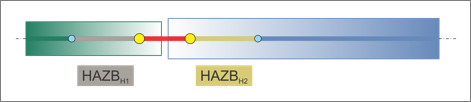
Dimensioning B
Figure 33. Dimensioning B Figure 34. Straight B Weld HAZ
Property and Material Info
The Property and Material Info parameters define the properties and materials of the
welds and the heat affected zones (HAZ).
HAZ Organize Scheme
Choose a HAZ organize scheme:
inherit property
Inherits the elements of the HAZ from the links in which the
HAZ elements are imprinted.
general property
Assigns the same HAZ property throughout one link, or
throughout all links.
Use the subsequent options to define how the properties are
determined.
individual property
Assigns individual properties to each HAZ.
HAZ Component Option
stay in original
Keeps HAZ elements in the component they were imprinted
into. No additional properties get created.
new component per original one
Creates a new component for each component that gets a HAZ
imprinted. The direct property assignment setting is ignored
when this option is selected.
HAZ Property Option
The options available are dependent on the HAZ Organize Scheme selected.
assign original property
Assigns the same property that was assigned to the original
components to new components.
assign duplicated property
Duplicates the original properties and assigns them to new
components.
select
Select a property from the current model via the Select
Property For HAZ option. Unless direct property assignment
is activated, a component named ltb_seam_quad_haz_ with the
property ID as a postfix is created.
same as original
Assigns HAZ elements the same property as the original. No
further properties are created. HAZ elements are organized
into components named ltb_seam_quad_haz_ with the property
ID as postfix.
scaled original thickness
Creates a new property and component for each link that has
a HAZ imprinted.
The property is a copy of the original. Properties are named
as ltb_seam_quad_haz_<linkname>_<scaled thickness>,
and components are named the same as the properties.
In addition, you can define the following:
HAZ thickness factor
Enables entering a factor to scale the
thickness.
HAZ Property Grouping
Groups properties in order to reduce the amount
of properties created.
Do not group
Prevents grouping.
group same thickness
Groups HAZ elements with the same thickness
into one property and component. HAZ elements of
T, L, and B welds are also grouped together if
they have the same thickness.
Properties are named
ltb_seam_quad_haz_<scaled thickness> or
ltb_seam_quad_haz_<property ID>, and components
use the same name as properties.
group same thickness within T, L, and B
Groups all HAZ elements with the same
thickness into one property and component, as long
as they have the same weld type of T, L, B.
Properties are named ltb_seam_quad_<t or l
or b>_<thickness>, and components use the same
name as properties.
input thickness
Creates a new property and component for each link that has
a HAZ imprinted.
The property is a copy of the original. Properties are named
ltb_seam_quad_haz_<linkname>_<scaled thickness>, and
components are named the same as the properties.
In addition, you can define the following:
HAZ thickness
Enables a factor for thickness to be
entered.
HAZ Property Grouping
Groups properties in order to reduce the amount
of properties created.
do not group
Prevents grouping.
group same thickness
Groups all HAZ elements with the same
thickness into one property and component. HAZ
elements of T, L, and B welds are also grouped
together if they have the same thickness.
Properties are named as
ltb_seam_quad_haz_<scaled thickness> or
ltb_seam_quad_haz_<property ID>, and components
use the same name as properties.
group same thickness
Within T, L, and B groups all HAZ elements
with the same thickness into one property and
component as long as they have the same weld type
of T, L, B.
Properties are named as ltb_seam_quad_<t or
l or b>_<thickness>, and components use the
same name as properties.
same as positive side
Guarantees the HAZ on the positive and negative side of the
T or L weld are assigned the same property.
same as the other size
Guarantees the HAZ on both sides of the B weld are assigned
the same property.
Weld Property
Define how the thicknesses for the different parts of the weld are
determined. Appropriate PSHELL properties are created.
Property Option For Vertical Quads
Property Calculation Method
PID
T Maximum
T Minimum
T1
T2
(T1 + T2)/2
(T1 + T2)
LH/sqrt(2)
(LH/sqrt(2) + LV/sqrt(2))/4
Same as Edge
*Property Factor
Property Option for Horizontal Quads
Property Calculation Method
PID
T Maximum
T Minimum
T1
T2
(T1 + T2)/2
(T1 + T2)
LH/sqrt(2)
(LH/sqrt(2) + LV/sqrt(2))/4
Thickness
*Property Factor
*Property Factor: Is a calculation factor that can be added to the
calculation. The default value is 1.0, so the thickness calculation
selection remains unchanged.
PID
Select a property from the current model via the Select
Property For Vertical Quad field. Unless direct property
assignment is activated, a component with the the name
ltb_seam_quad_weld_ and the property ID as postfix is
created.
Lh/sqrt(2)
Determines the thicknesses of welds. Options are dependent
on the weld type (T, L, B) and the selected weld shapes
(vertical, angled, vertical and angled).
(Lh/sqrt(2)+Lv/sqrt(2))/4
Properties are named
ltb_seam_quad_weld_<weldshape>_<link1>_<link2>_<thickness>,
and components are named the same as the properties and host
the weld elements. Lh is the superset of LLH and LTH (see
dimensions above). Lv is the superset of LLV and LTV (see
dimensions above).
same as edge
Inherits the property of the link with the free edge for the
vertical weld. Unless direct property assignment is
activated, a component with the name ltb_seam_quad_weld_
with the property ID as postfix is created.
input thickness
Creates properties with the required thicknesses for each
link combination and weld shape (vertical, angled,
straight). The properties are named
ltb_seam_quad_weld_<weldshape>_<link1>_<link2>_<thickness>,
and the corresponding components are named the same as the
properties and host the weld elements.
Weld Property Grouping
Reduce the number of properties created by grouping them, except when
using the select and same as edge options.
do not group
No grouping will take place. Properties are created as
described in previous options.
group same thickness
Groups all weld elements with the same thickness into one
property and one associated component. Vertical, angled, and
straight weld elements that have the same thickness are also
grouped together.
Properties are named ltb_seam_quad_weld_<thickness>, and
their associated components are named the same as the
property.
group same thickness within vertical, angled + capped and
straight quads
Groups all weld elements with the same thickness and weld
shape (vertical, angled + capped, straight) into one
property and one associated component.
Properties are named ltb_seam_quad_<vertical or
angled_capped or straight>_<thickness>, and their
associated components are named the same as the
property.
By Weld If Possible
Create components per Connector.
Direct Property Assignment
Stops additional components from being created, and directly assigns
created or selected properties to individual weld or HAZ elements.
Behavior
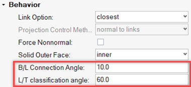
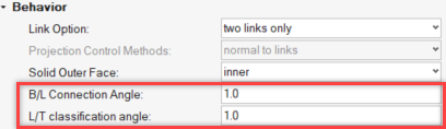
B/L classification angle
Angle that is automatically determined for each individual seam
connector, whether it is to be considered a butt weld or a lap weld.
Default is set to 10.0°.
If the angle of the two links is smaller than the B/L classification
angle, then it will be considered a butt weld and a lap weld; a further
check determines whether the links overlap. If the links do not overlap,
a butt-weld is performed.
L/T classification angle
Angle that is automatically determined for each individual seam
connector, whether it is to be considered a lap weld or a t-weld.
Default is set to 10.0°.
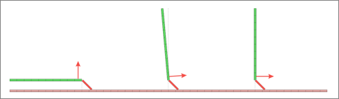
Angle Direction
Defines which side the angled weld elements are created.
connector side
Angled weld elements are created on the side where the
connector is located, as long as the connector is not
perfectly on the free edge.
If the connector is on the free edge, the edge quad normal
option will be automatically used.
positive side/negative side
The positive and negative side can be determined as long as
the links are not perfectly perpendicular to each other.Figure 35. . Overview of how the positive and negative side is
determined. When links are perfectly perpendicular,
the edge quad normal option is automatically
used.
edge quad normal
Figure 36. . Overview of how the side for the angled weld is
determined. If the normal directions are reversed,
the side of the angled weld changes.
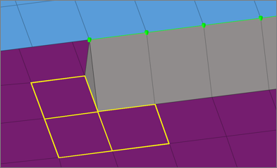
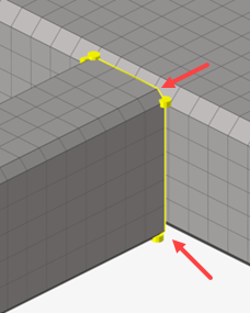
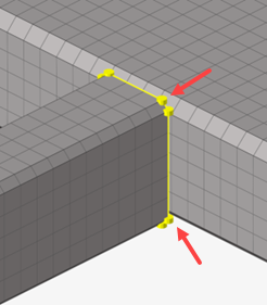
Snapping to Edge
Automatic edge snapping can be used to precisely position connectors.
First, the connector snaps to, for example, the closest free edge, then
the projection and FE creation starts.
The snapping distance can be defined separately for T, L and B
connections.
You can choose whether to snap to:
maximum 1 element row
maximum 2 element rows
no (connector does not snap)
Figure 37. Original Model before Realization. Initial situation with one element row marked for
the lap weld and two element rows for the t
weld.
Figure 38. Edge Snapping Enabled
Figure 39. Edge Snapping Disabled
Edge Treatment (T/B)
Attempts to create specific vertical lengths for T connections LTV, and
specific lengths for B connections LB.
Only enabled when the Edge Treatment setting is enabled from the Realization Details settings.
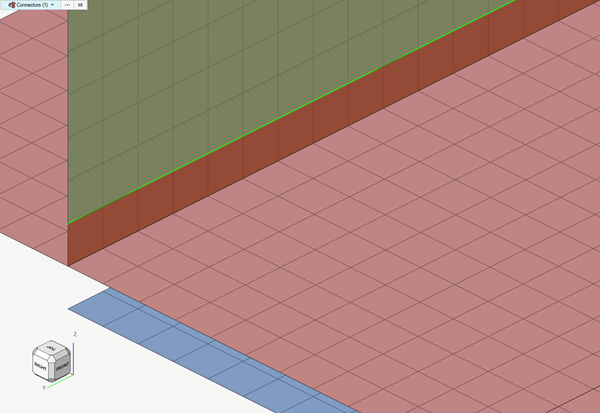
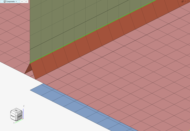
Figure 40. Original Model before Realization
Figure 41. Realization using Edge Treatment. Free edges were contracted or extended.
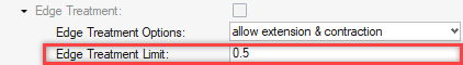
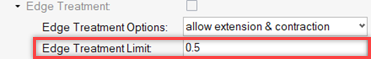
Edge Treatment Options
Choose whether to:
extension and contraction
extension
contraction
Edge Treatment Limit
Edge treatment is a pure node movement; therefore, the maximum movement
needs to be limited to prevent the elements at the edge from being
destroyed. Movement is limited to a maximum of 0.5 times the element
size at the edge. 0.5 is the maximum allowed value and default
value.
Preserve Washer
Controls how washers are preserved during the seam imprint
realization.
Figure 42. Original Mode with Perfectly Meshed
Washers
Figure 43. No Washer Preservation Enabled. Washers have been opened.
Figure 44. Washer Preservation and Remesh Enabled. Washers are still intact, but the mesh seeding has
been modified.
Figure 45. Washer Preservation and No Remesh Enabled. The washers have been fully preserved.
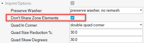
Do Not Share Zone Elements
Seam imprint allows heat affected zones (HAZ) to be merged in close
areas. In this situation, one element might touch the weld elements from
two different connectors. Do not share zone elements prevents zone
elements from being shared.
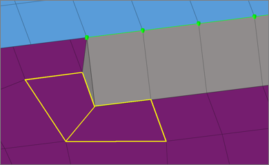
Quad In Corner
Controls whether a single or double element is created in corners of
quad seam connectors with a certain vertex.
A angle must be defined for a single quad corner. If the corner angle is
greater than the defined angle, a double quad corner is created.Figure 46. Quad in Corner. A double quad corner is shown on the left, and a single quad
corner is shown on the right.
Quad Control
Controls the maximum deviation from the perfect quad element for the
heat affected zone (HAZ). It can be controlled, if the element size or
the element skew is more important to retain.
Max Quadsize Reduction In % / Max Quad Skew In Degrees
Figure 47. Max Quad Size Reduction: 80.0 / Max Quad Skew:
5.0
Figure 48. Max Quad Size Reduction: 5.0 / Max Quad Skew:
45.0
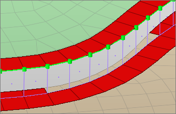
Silver Elements
Sliver elements are small elements that you may not want in your model.
In the images below, a perfect perpendicular projection resulted in
sliver elements. The Sliver Elements setting can be used to manage
sliver elements in your model. In the images below, the red elements
represent the HAZ elements.
Figure 49. Allow
Figure 50. Prevent by Moving Projection Points
Figure 51. Prevent by Moving Edge
Figure 52. Delete Sliver Elements
Element length<
This length controls which elements to treat as sliver elements.
Feature Angle
Determines important features to retain during the imprint. Features
that cross the HAZ, as well as near by features cannot be retained.
Seam Test Point Alignment
A global option. If the seam connectors are close by activating “Seam
test Points Alignment” option in connector entity editor, the test point
alignment is based on the proximity of other connectors to get better
mesh flow. It also ensures the cross-over connector should have a common
test point, so that unique nodes will be created.
Seam Loose Ends
A local option set on individual connectors. Enabling “Seam Test Points
Alignment” will also enable this option, which allows for the alignment
of start and end points of seam connectors along with alignment of other
test points.
Seam Fixed
A local option set on individual connectors. Enabling the “Seam Fixed”
option considers all the test points of seam connectors as fixed and
will not be disturbed.
Seam Consider Feature and Boundaries
A local option set on individual connectors. Enabling the "Seam Consider
Feature and Boundaries" option will adjust test points so the
projections fall on features/boundaries wherever possible. Overhanging
test points will be trimmed.Figure 53. Without Seam Consider Feature and Boundary Figure 54. With Seam Consider Feature and Boundary
Partial Imprint Percentage
The allowable percentage of the connector to realize and still be
classified as "Realized".
Profile Welding Use Case
For models that have profile sections that need to be welded, there is often a
requirement for vertical/straight seams.
By using Seam Quad connectors, this can be achieved. Below is an explanation of the
options that need to be defined to achieve this, as well as some tips and example
cases.
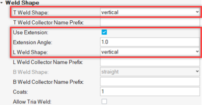
Define the Control
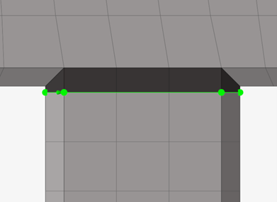
For the shape of the weld, only vertical shapes for both T and
L type connections needs to be defined.
Use Extension is selected. A low value is defined for this
option (in most cases a value of 1 is sufficient). This will ensure that the
projection is kept straight.
Figure 55. Weld Shape
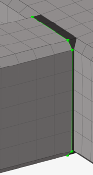
It is also recommended that Use Edge for T, B is selected. If
precise dimensions for the welds is not needed, then this option should be
selected.
Figure 56. Realization Details
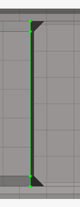
Since Use Extension is selected, the B/L and L/T
Classification angle must also be changed. These values should be the same value as
the Extension Angle value. By doing this, it is ensured that the connections will be
treated as T-type and straight quads will be projected.
Figure 57.
All other options can be left to the default values or changed according to specific
needs.
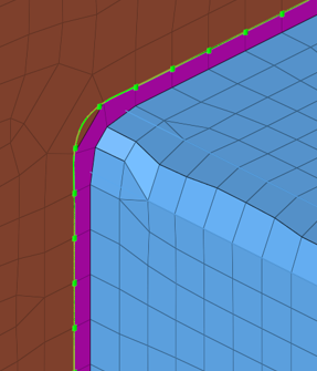
Imprinting Significant Nodes
From the Connectors ribbon, select the Imprint tool.Figure 58.
Before realizing the connector, you should also imprint any corner nodes that do not
appear as significant points. When imprinting these corner nodes on the connector,
they act as significant points. Therefore, they ensure that during the projection,
the corners will be retained, and the projection will be kept straight.
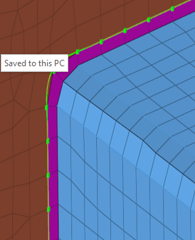
Examples showcasing the realization of the controller described in this use case.Figure 61. Figure 62. Figure 63.
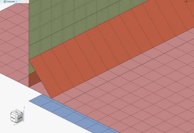
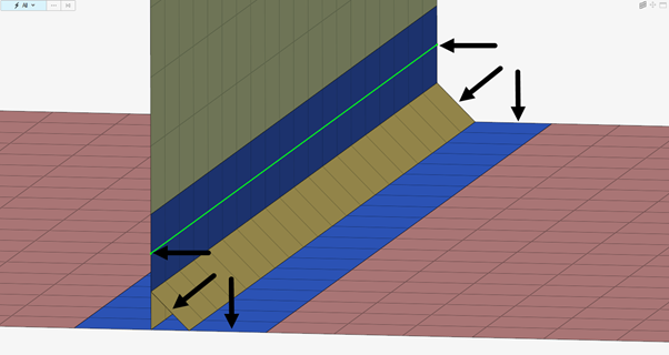
Fillet Weld Use Case
Explore welded connections between a fillet and plane using Seam-Quad
connectors.
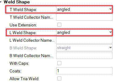
Define the Control
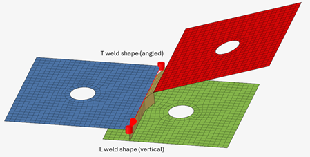
Figure 64. Weld Shape For T Weld Shape, an angled shape is usual for these
use cases. To avoid errors, ensure that both T and L weld shapes match.
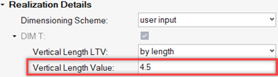
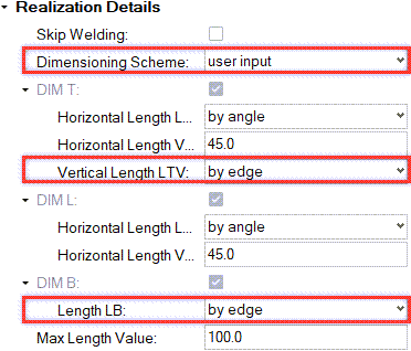
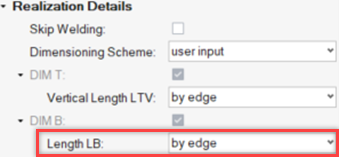
Figure 65. Realization Details
The required dimensions for the welds must be defined. For applications that require
specific dimensions, you can set them directly by selecting user
input for Dimensioning Scheme. To avoid errors, it is recommended
that the by edge option is used to define the vertical length
for T and B type connections.
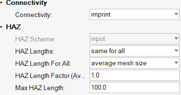
Figure 66. Connectivity and HAZ
Define the connectivity and HAZ options. If the HAZ zone is not necessary, it is
recommended to use the Imprint/no HAZ option for Connectivity
to avoid imprinting errors. In cases where the HAZ zone is critical, the dimensions
can be tailored to specific needs.
All other options can be left to the default values or changed according to specific
needs.
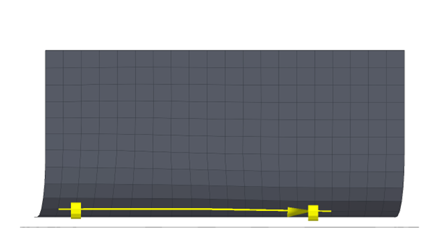
Create the Connector
The connector must be created on the fillet part to realize correctly.Figure 67.
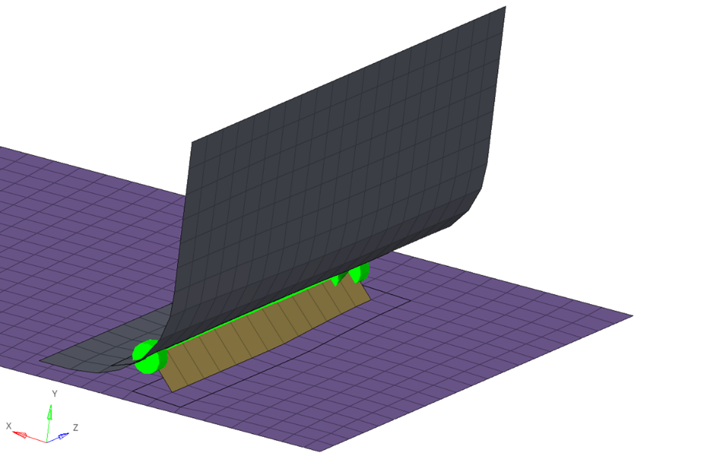
Examples
The following images showcase the realization of the connector defined in this use
case.Figure 68. Figure 69. Figure 70.
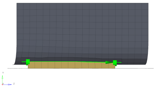
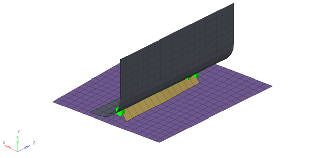
Self-Connecting Weld Use Case
Learn how to realize self-connecting welds. This is a common case where you need to
weld the gap in one part instead of connecting multiple parts.
Define the Control
Tolerance
Figure 71. A correct tolerance value is the most important option to define
for this use case. The tolerance should be small to ensure that the
projections will be made on the same part.
In this case, the tolerance is set to be 1. This is done after
inspecting the distance of the gap where the connector should
realize.Figure 72.
Realization Details
Figure 73. Define the length of the quads to be computed using available
edges. This ensures that you do not move the edges but realize our weld
in the available gap.
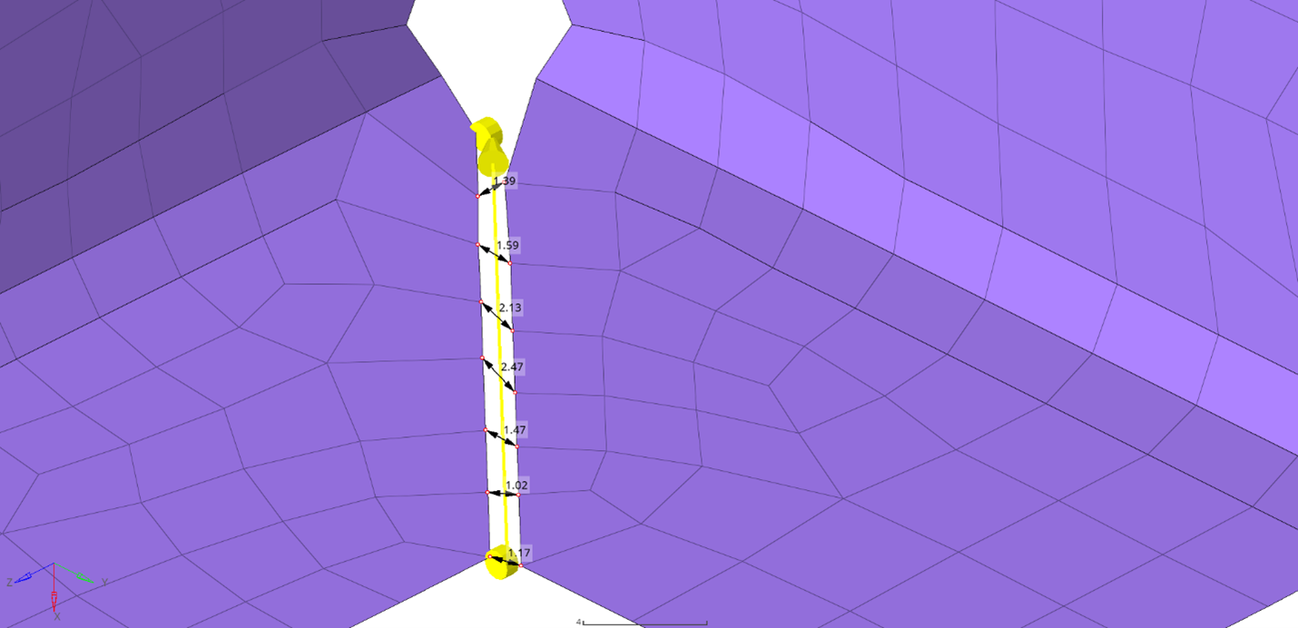
Example
Figure 74
showcases the realization of the connector that was defined.
Figure 74.
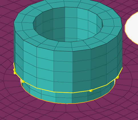
Solid-Shell Use Case
Use Seam Quad to create a connection between a model's solid and shell
elements.
Some models use both solid and shell elements. In these models, you may need to
create a seam connection between a part that is modeled using solid elements and
another modeled with shell elements. Use Seam Quad to create a successful
realization for this use case.
The following sections explain the options to define in the control as well as the
steps to create the connector entity.
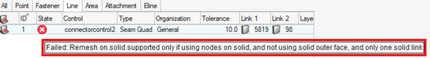
If the connector fails, the following error message is displayed:Figure 75.
Note: Seam Quad does not support imprint on solid
elements. This limitation requires specific steps for creating the connector and
tuning the control.
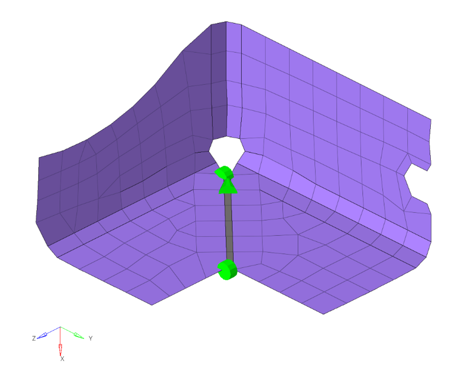
Create the Connector
From the Connectors ribbon, click the Line tool.Figure 76.
From the guide bar, select the required
nodes on the solid elements. Press or to continue or exit the context.
Figure 77. A line connector created from nodes on the solid
elements.
Define the Control
Set the appropriate tolerance according to the distance between the parts.
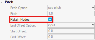
Under Pitch, select Retain Nodes. This option ensures
no errors occur from the connector trying to imprint on solid elements.
Figure 78. Retain Nodes selected
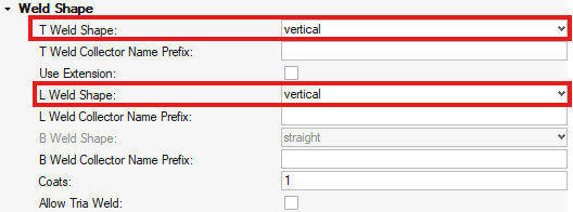
For Weld Shape, select vertical for the T and L weld shapes.
Figure 79. Vertical weld shape for T and L welds
Select the Use Edge for T, B option. With this
option, the nodes on the solid elements’ edge are used to determine the weld
length.
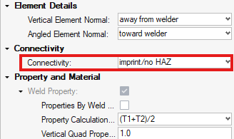
For Connectivity, select imprint/no HAZ. This option
ensures that no errors occur from the connector trying to imprint on the
solid elements.
Figure 80. Imprint/no HAZ option
Optional Steps
As stated previously, Seam Quad has a limitation regarding imprinting on solid
elements. However, this does not limit you from using the imprinting capabilities
for the shell elements in the realization.
For Connectivity, select imprint.
By default, this
creates Heat Affected Zones (HAZ) that are imprinted on both solid and
shell links. For this particular use case, imprinting a HAZ on the solid
elements must be avoided.
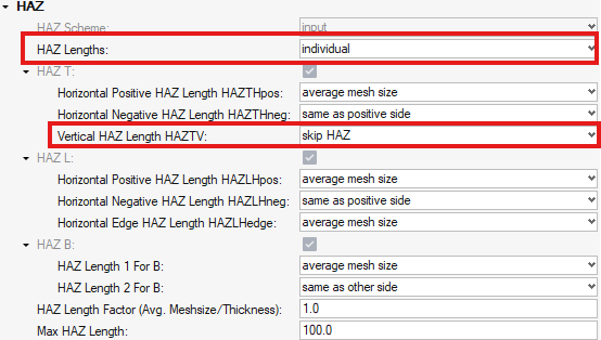
Under HAZ options > HAZ Lengths, select individual.
You can now
select the dimensions of the created HAZ per weld shape and length.
According to the weld configuration, select skip HAZ
on the position of the weld that corresponds to the solid elements, for each
T, L, or B welds.Figure 81. Skip the vertical side HAZ for T welds
Define the dimensioning scheme (average mesh size, input, by thickness) to
adjust the realization to the requirements.
Examples
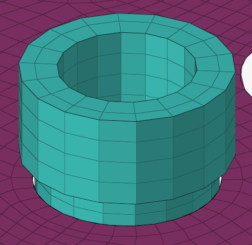
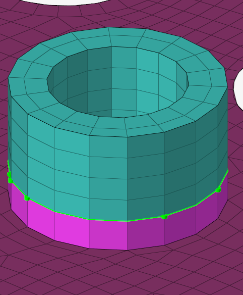
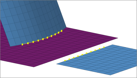
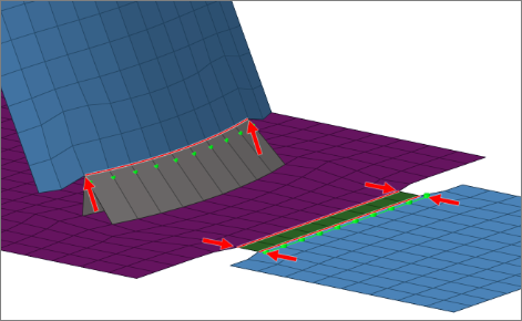
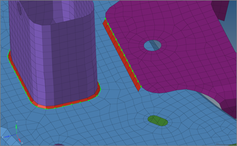
In the first example, a tubular part is modeled using solid elements and must be
connected to the plate part, which is modeled with shell elements.
The connector is created on the edge of the solid elements and is realized using the
options described above.Figure 82. Initial model Figure 83. Realized seam quad between solid and shell elements
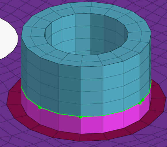
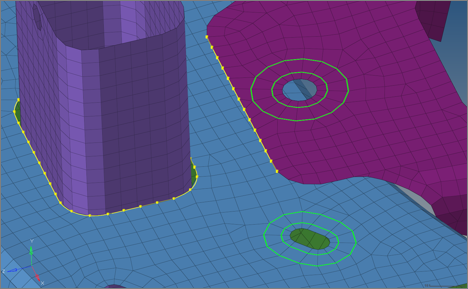
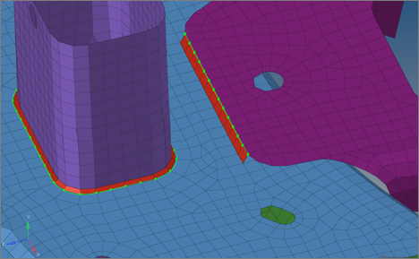
Next, the same connection is realized using imprint only for
the shell elements’ side.Figure 84. Using imprint with HAZ only on the shell elements
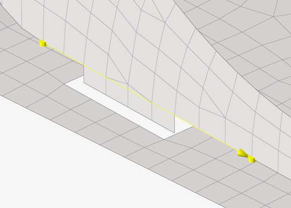
Tab/Slot Use Case
For models that contain tabs and slots, straight seams are required to model the
connections.
Seam Quad can be used to successfully realize such cases. There is an explanation
below of how the control can be setup to realize the connector.
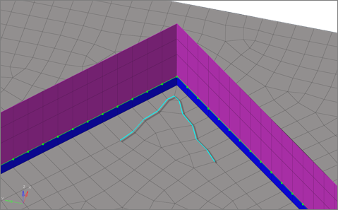
Create the Connector
Choose the Line tool and select the nodes for the creation of the connector from the
guide bar. It is recommended the line connector extends
on both sides of the slot.Figure 85. Creation of Line Connector
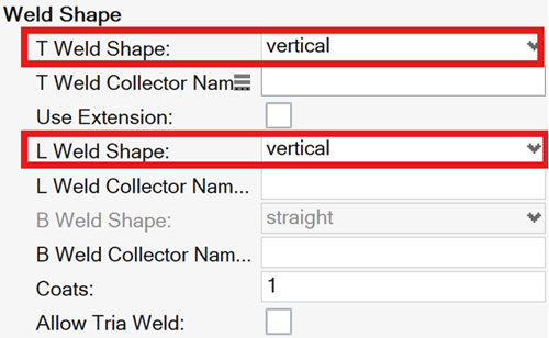
Define the Control
For the shape of the weld, only vertical shapes for both T and L type connections
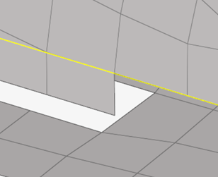
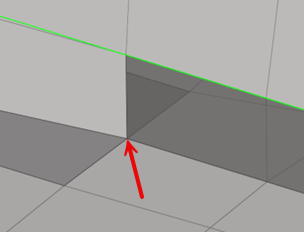
need to be defined.Figure 86. Weld Shape For connectivity, Seam Quad can be realized with and without Heat Affected
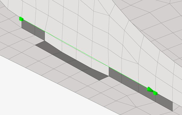
Zones (HAZ).
In case no HAZ is desired, select imprint/no HAZ.
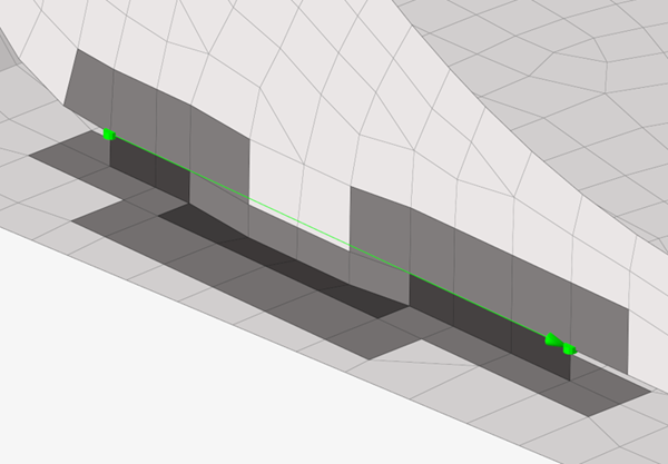
In case HAZ is required, select imprint. The HAZ will be
created on both the tab and around the slot.Figure 87. Tab/Slot Realization without Haz Figure 88. Tab/Slot Realization with HAZ Figure 89. Tab/Slot Realization with HAZ Top View
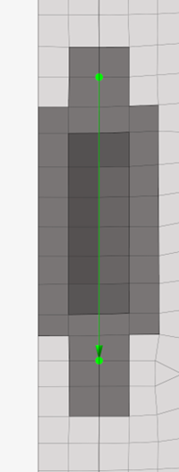
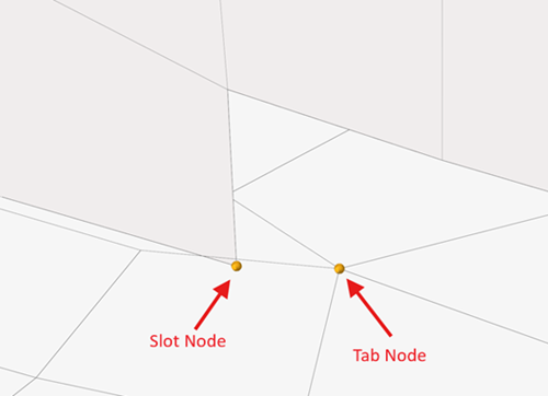
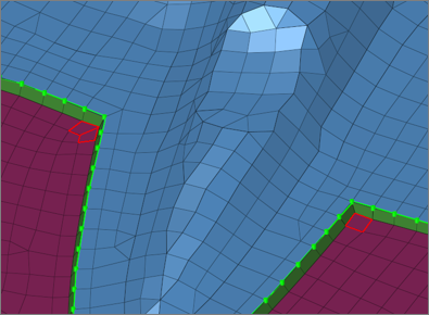
Note: During realization, the nodes along the tab’s edges will be made
equivalent to the slot’s middle node. In case there is no tab mode, the slot
elements during the realization will be split and connected to the slot
node.Figure 90. Tab and Slot Nodes to be Made Equivalent Figure 91. No Slot Node Before Realization Figure 92. Slot Node Created and Made Equivalent with Tab Node
Troubleshooting
Learn more about connector error messages, causes, and workarounds.
Specific Guidelines
Message
Reason and Workaround
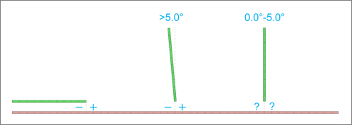
Connection classified as x, control defined as T/L/B.
Reason
Using Seam Quad connectors with Weld Type = “T/L/B
connection”, when the angle between the links is not
classified as the same connection type.Figure 93. Figure 94.
Workaround
Change the Weld Type to Automatic type
based on angle or change the
classification angles to match your
requirements.
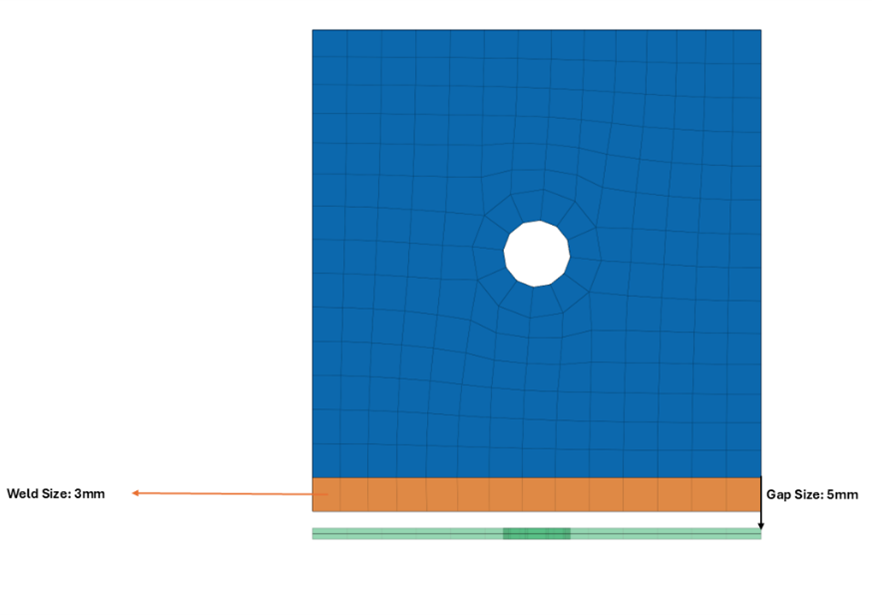
The edge treatment required for the weld size definition, is
more than the edge treatment limit.
Reason
Edge treatment will attempt to move the edge nodes
of the source part to create the required weld size.
This movement is limited by the Edge Treatment Limit
option, which is a fraction applied to the mean
element size. In cases where the gap between the
links is greater than the edge treatment limit plus
weld size, the connection fails.Figure 95. Figure 96. Figure 97. In Figure 101, to realize the connection, the edge needs to
move by 2mm, but the Edge Treatment Limit is set to
1.5mm. Thus, the connection fails.
Workaround
To counter this problem you can complete any of the following:
Change the weld size
Change the connection to be between edges
Change the edge treatment limit to allow more
node displacement
Figure 98. Figure 99. Figure 100.
Workaround
Change the Weld Type to Automatic type
based on angle or change the
classification angles to match your
requirements.
The edge treatment required for the weld size definition, is
more than the edge treatment limit.
Reason
Edge treatment will attempt to move the edge nodes
of the source part to create the required weld size.
This movement is limited by the Edge Treatment Limit
option, which is a fraction applied to the mean
element size. In cases where the gap between the
links is greater than the edge treatment limit plus
weld size, the connection fails.Figure 101. Figure 102. Figure 103. In Figure 101, to realize the connection, the edge needs to
move by 2mm, but the Edge Treatment Limit is set to
1.5mm. Thus, the connection fails.
Workaround
To counter this problem you can complete any of the following:
Change the weld size
Change the connection to be between edges
Change the edge treatment limit to allow more
node displacement
Figure 104. Figure 105. Figure 106.
Required weld size is smaller than the distance between the
links.
Reason
When the weld size is smaller than the distance
between the links and no edge treatment is allowed,
then the weld size cannot be satisfied, and the
connection fails.Figure 107.
Workaround
Change the weld size dimensions or move the links so
the weld size can be satisfied.
Automatic weld type does not support transitioning between
different weld shapes.
Reason
This error occurs for a single line connector, in
cases where the Weld Type is set to
Automatic type based on
angle and the weld shapes for the
different weld types do not match. In such cases the
connector will try to create different weld shapes
for the different links (based on the link angles)
which is not supported.Figure 108. Figure 109. Figure 110.
Workaround
Change the Weld Shapes to match each other or change
the Weld Type to the preferred one instead of
Automatic type based on
angle.
The connector's link entity lacks the required
thickness.
Reason
This error is raised when the connector control uses
the thickness of the links to determine the
realization of the connection, and the links lack a
SHELL property. In the case of seam-quad connectors,
this can occur when using a thickness dependent
dimensioning scheme.Figure 111.
Workaround
Assign a SHELL property on the connector links
with the appropriate thickness defined.
Change the connector control to not use the
thickness of the links for the realization.
Quad transition error: allow sharing of zone elements between
connectors.
Reason
Two or more seam-quad realizations have common
elements that overlap.Figure 112.
Workaround
Clear the Don’t Share Zone
Elements option or trim the connectors
to not overlap.
Quad transition error: 1-D elems are present very close to
the connector imprint line Please remove the 1-D elems from
connector imprint area.
Reason
This error is raised when a connection tries to
realize close to 1-D elements that influence the
realization.
Workaround
Remove the 1-D elements that are near the
realization area.
Quad transition error: Connector meshing failed.
Reason
This error is triggered when the creation of the
elements fails during the imprinting process. There
are many reasons for this error to occur.
Workaround
Switch the Connectivity option from
imprint to
imprint/no HAZ.
Change the HAZ dimensions.
Figure 113. Figure 114. Figure 115.
General Guidelines
Quad transition errors occur during the imprinting process when realizing the
connector. There are a number of these errors, and they can be triggered by various
factors. Due to this, it is difficult to document them similarly to the Seam Quad
specific errors above.
Here are some best practices that can help you avoid these Quad transition errors and
can lead to a successful realization:
In most cases, errors are due to poor quality mesh. Ensuring the underlying
mesh, for all links, has good quality is crucial when realizing Seam Quad
connectors. You can conduct a Rebuild operation before realizing the
connectors.
When unnecessary, it is recommended to not use HAZ zones when realizing the
connector. During Imprinting, the HAZ region must be imprinted on the links.
In some cases, there is not enough space for the HAZ region to properly
imprint. Changing this option often results in a successful
realization.
Features that are in the imprinting area of the connector create problems
during imprinting. You can adjust the weld size as well as the location of
the connector to work around such features.


 or
or  to continue or exit the context.