Solid
Realization Details
- Solid Type
-
Figure 1. Pattern 1: Tapered Bolt 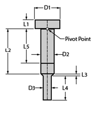
Figure 2. Pattern 2: Tapered Bolt with Washer 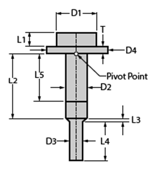
Figure 3. Pattern 3: Straight Bolt 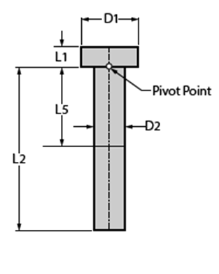
Figure 4. Pattern 4: Straight Bolt with Washer 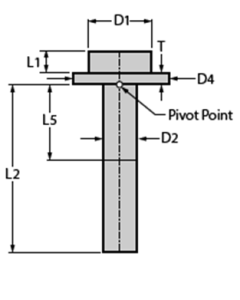
Figure 5. Pattern 5: Double Sided Bolt 
Figure 6. Pattern 6: Double Sided Bolt with Washers 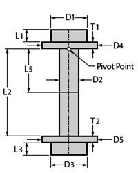
- D1
- Diameter of the bolt head.
- D2
-
- Input
- A manually defined diameter of the bolt shaft.
- Auto
- The connector will automatically take the diameter of the smallest hole and set it as the diameter of the bolt shaft.
- D3 (Patterns 1, 2, 5, and 6 only)
- The diameter of the tapered section of the bolt (pattern 1 and 2), or the diameter of the double-sided bolt (patterns 5 and 6).
- D4 (Patterns 2 and 4 only)
- Diameter of the washer.
- D5 (Pattern 6 only)
- Diameter of the double-sided washer.
- L1
- Length of the bolt head, excludes the thickness of the washer.
- L2
- Length of the main section of the shaft of the bolt.
- L3
- Transition zone between the tapered section of the shaft of the bolt and the main shaft of the bolt, or the length of the double-sided bolt head excluding the thickness of the washer (pattern 6).
- L4 (Patterns 1 and 2 Only)
- The length of the tapered section of the bolt (patterns 1 and 2), or the length of the double-sided bolt (pattern 5).
- L5
- The position of the pretension section.
- T (Patterns 2 and 4 only)
- The thickness of the washer.
- T1 (Pattern 6 only)
- The thickness of the washer.
- T2 (Pattern 6 only)
- The thickness of the double-sided washer.
- Mesh Type
- Use this option to change between a Hex or a Tet Mesh for the bolt.
- Mesh Size
- Use this option to define the mesh size down the length of the bolt.
- Mesh Density
- Use this option to define the mesh density around the circumference of the bolt.
- Evaluation Surfaces
- Use this option to create finer mesh areas and element sets near the bolt head.
-
- Number of Layers
- Specify the number of element layers to be divided down the shaft length.
- Divisions per Layer
- Specify the number of divisions per element layer.
Figure 7. Definitions for Number of Layers and Divisions per Layer options. In this example, Number of Layers=1 and Divisions per Layer=3. 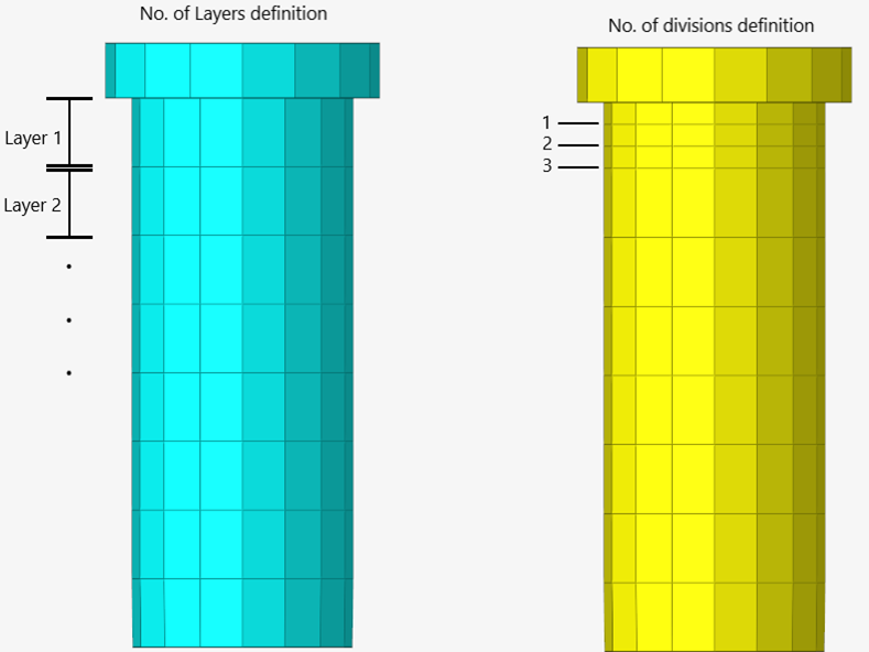
- Pretension
- An optional parameter that will create a pretension section.
- Shell Offset
- Use this option to consider the thickness of shell elements when
calculating the bolt’s body length (L2). For patterns with a
double-sided head, the shell offset option applies to both sides.
Figure 8. Shell Offset option 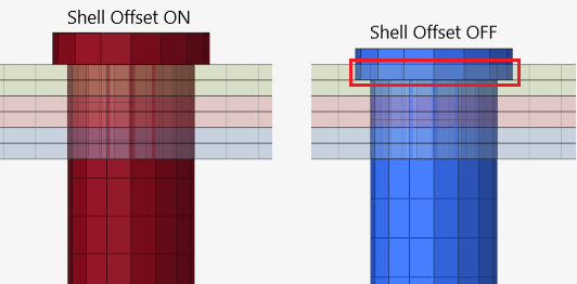
- Cross Section
- Use this option to define the number of cross sections to be created down the bolt length.
- Failure (LS-DYNA Only)
- This will create a layer of elements under the head of the bolt with
hour glassing and a rupture material so the failure of the bolt can be
modeled.
Figure 9. 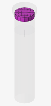
- Rupture Material
- An optional selector that can be used to define an existing material for the failure elements. If left empty, a new material will be created for the realization.
Contact
Contact is created for all solver profiles automatically.
- Explicit Solver Interfaces
- For explicit solver interfaces (LS-DYNA and
Radioss), there are no contact options.
The entire bolt and links are placed into a contact set. The shaft of
the bolt is tied into the last link.
Figure 10. 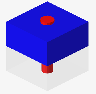
Figure 11. 
- Implicit Solver Interfaces
- For the Implicit solver interfaces (OptiStruct, Abaqus, and Nastran), under the head of the bolt is modeled separately as a contact. For
patterns with a double-sided head, contact is created for both
sides.
Figure 12. 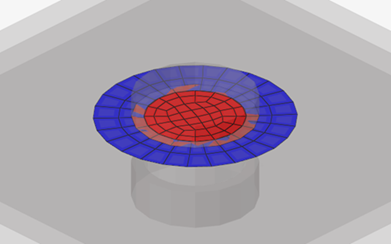
- Shaft Contact Type: (OptiStruct/Abaqus/Nastran only)
-
- Tied
- A tied contact is created for the shaft of the bolt and the
last link of the connector.
Figure 13. 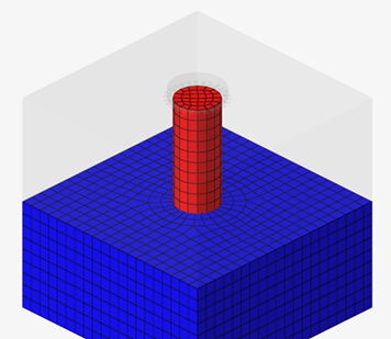
- Threaded (Solid Links Only)
-
- Last Part
- A contact patch will be created between the
inner face of the solid hole and the face of the
bolt shaft.
Figure 14. 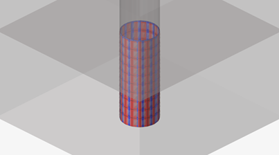
- Contact Length
- Measured from the bottom of the bolt, the
contact thread on the bolt will be the specified
thread length.
Figure 15. 