Clip
The bolt (metal clip) creates elements, systems, and configurable body elements that connect a clip location.
To correctly determine the connector's face and the elements that are a part of the projection, you are required to select a node on the base where there is a hole for the penetrating part.
Realization Details
Clip Type
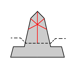
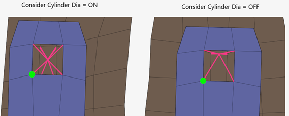
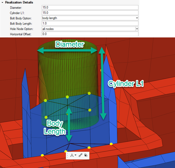
The Diameter, Length 1 and 2, Bolt Length, Hole Node Option, and Horizontal Offset options, defined in Figure 5, control the node selection for the parts being clipped.
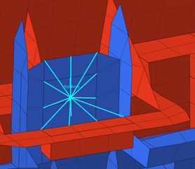
The number of elements that are selected for the realization on the loop part (red) is controlled by the width of the diameter. The diameter also controls the number of nodes selected in the penetrating part (blue).
The Length 1 option controls the height of the search Cylinder.
The Length 2 option controls the vertical offset of the search Cylinder (pattern 3 only).
The Body Length option can be set to "hole gap" or a defined body length. A defined body length will create the body element from the base element up the desired length (See graphic below). Hole gap length will create a body element from the centre of the found groups of elements.
The Hole Node option specifies how the depended nodes will be determined.
- All nodes
- All the nodes of the hole will be considered as depended nodes for the element.
- Dia factor
- A diameter factor is specified which, after being multiplied with the Diameter value, determines the diameter within which the nodes will be considered.
Material Option
When defining the connector, the Material Option can be selected for individual connectors using the Connector Entity Editor.
- From current model
- Select an existing material from the current model.
- From search folder (default)
- For bolt (metal clip) realizations, the material search folder is Metal_clip. HyperMesh searches for this folder in the following locations and in the following order:
- From connector metadata
- Once a connector is realized with the Material Option “From Search Folder”, the folder and file name are written as metadata to the connector. Folder data is saved in a relative manner to allow the exact same re-realization in a different work environment as long as the materials are saved in the according folders
Body Configurations
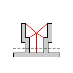
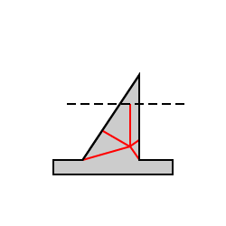
All the realizations support multiple body options.
The most notable differences are between the rigid elements and the deformable elements. The rigid will create a single element for the whole realization.
 |
 |
| Solver | Supported Types |
|---|---|
| LS-DYNA | BEAM, Rdgbody |
| Nastran / OptiStruct | CBUSH, CBAR, RBE2 |
| PAM-CRASH 2G | SPRGBM, SPRING, RdgBody |
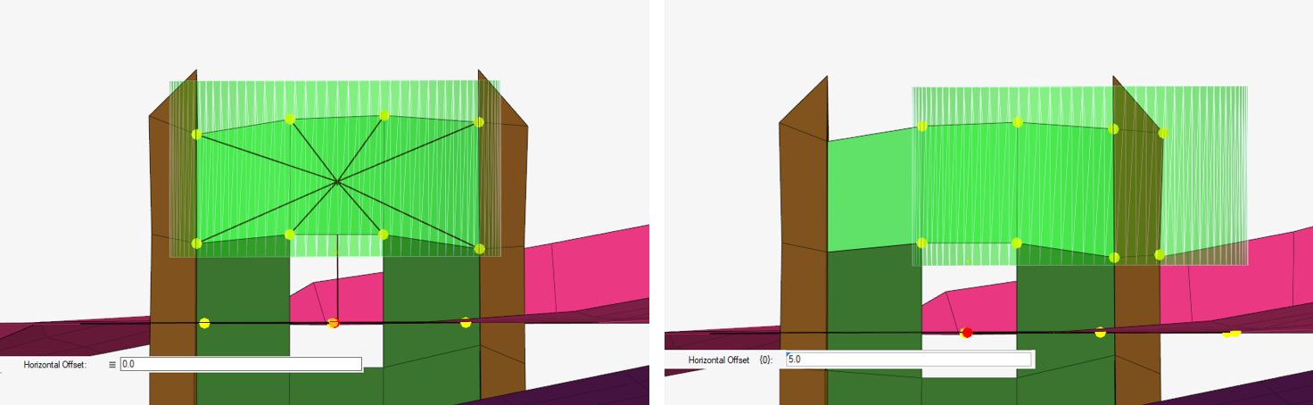
In Figure 9, the Spring/Body element is offset horizontally to indicate the "crisscross" configuration.