FBD Create and Edit
Use the Free-Body Create tool to create and edit free-body section entities.
A free-body section entity can be defined by selecting a group of elements which will give a contribution of forces and moments at selected interface nodes. A free-body section can also be defined by a cutting plane in space, finite or infinite, with optional limitation of contributing parts.
In each section, you can define the summation point location and the system used by the section to resolve forces and moments components. The definition of multiple free body sections can be saved in a template file (*.csv file) and can be imported in another session later.
Create a Mesh Based Section
-
From the Post ribbon, select the Create Free-Body
tool.
Figure 1. 
- From the guide bar, verify Mesh is selected.
-
From the guide bar, select
Elements and select elements to account for in the
modeling window.
The location is defined.
A new entity is created and edit mode is activated for the entity.
The icon on the guide bar is populated.
Tip:- If the tool is called from idle mode with the element selector populated, the selection is propagated as location.
- In edit mode, click
 from the
guide bar to fit to entity location.
from the
guide bar to fit to entity location. - Resetting elements turns the entity into an invalid state since location is a mandatory selection. The entity will remain invalid until new elements are selected. Leaving the tool will not commit the change to the database and the last element selection is restored as location.
- Optional:
From the guide bar, select Nodes
and select interface nodes in the modeling window.
The force and moment will be extracted from these interface nodes when using the Plot tool. Only the elements selected in location can contribute to interface nodes.
If no nodes are selected, then all nodes of the selected location will be considered.
Nodes not belonging to location elements are filtered out.
- Optional:
From the guide bar, select the Boundary
Nodes check box.
Free nodes and nodes shared with other elements not part of location are selected.
The interface node selector is disabled.
As location updates interface nodes, elements selection is changed.
- Optional:
From the microdialog, select the system in which force
and moment components are extracted.
- Click
 to use node output
system.
to use node output
system. - Unselect to set resolved-in
to the basic system.
- Click
 to select a local
system to resolve in.
to select a local
system to resolve in.
- Click
- Optional:
From the microdialog, select the summation
location.
- Click
 to use the section
geometric center.
to use the section
geometric center. - Click
 to pick a node to
reference the node ID as summation point or change the selector type to
Location and pick a location in space to save X,
Y, Z coordinates.
to pick a node to
reference the node ID as summation point or change the selector type to
Location and pick a location in space to save X,
Y, Z coordinates. - Click
 to pick another
location to update or change the selector type to
Node and select a node ID to save as summation
point.Restriction: This option is only available when Edit mode of a free-body section using a summation (X, Y, Z) location.
to pick another
location to update or change the selector type to
Node and select a node ID to save as summation
point.Restriction: This option is only available when Edit mode of a free-body section using a summation (X, Y, Z) location.
- Click
-
From the guide bar, click
 to apply the updates
and remain in the tool or click
to apply the updates
and remain in the tool or click  to apply the updates
and exit the tool.
to apply the updates
and exit the tool.
Create a Infinite or Finite Cut Section
-
From the Post ribbon, select the Free-Body Create
tool.
Figure 2.
- From the guide bar, select Finite Cut or Infinite Cut.
-
Select a plane.
-
Define the plane normal by using the frame rotate manipulators on each
edge to change the orientation and size.
Tip: Plane manipulator tips:
- You can change the plane base point coordinates by clicking
 in the microdialog.
 - You can click
 to display the vector tool manipulator on top of the
plane frame.
to display the vector tool manipulator on top of the
plane frame. - You can pick a vector handle:
- Select
 to control the point global coordinates in
space.
to control the point global coordinates in
space. - Select
 to provide plane normal components.
- Select
- You can pick corners to change plane manipulator size independently or keeping the ratio.
With Infinite Cut, the plane preview always shows the intersection with the entire model even if some parts are not displayed.
- You can change the plane base point coordinates by clicking
-
Define the plane normal by using the frame rotate manipulators on each
edge to change the orientation and size.
-
Define plane orientation.
The plane local system defined with dataname Orientation is equivalent to the Resolved-in field available in mesh based sections. The plane normal acts as local z-axis.
-
Click to open the vector tool.
-
Click
 to open the move tool.
- Rotate the x-axis of the manipulator to fully define the local system onto which results will be resolved.
-
Click
-
For Finite plane, define the plane size.
- Select a plane frame to activate its handles.
- Select a corner to change its position.
- In the microdialog, define the plane length and width.
- Optional:
Select intersected entities.
By default, the section will try to intersect all entities in the model (even if not displayed) with the plane defined (Finite or Infinite). It is possible to limit the intersection to only a few components or parts.
- From the guide bar, select Component or Part as the entity type.
- Pick entities to consider in section cut.
- Optional:
In the microdialog, define the plane thickness.
Plane thickness acts as centered tolerance to capture on-plane nodes.
The plane thickness defaults to twice as great as node tolerance.
The last value used is retained as the default for the next session.
The plane thickness increases the number of nodes considered in-plane. Increasing thickness to a very large value can’t exceed the region defined by the nodes of intersected elements.
- Optional:
From the Entity Editor, select
Include for Rigids.
By default, rigids elements connected to nodes found as interface nodes are excluded. It is possible to force HyperMesh to include rigid elements in contributing elements connected to nodes. When converting a section to a mesh based section (see Create a Mesh Based Section), rigids will be included or excluded based on this selector.
- Optional:
Select summation location.
- Click to use the section
geometric center on plane.
- Click to pick a node to
reference the node ID as summation point or change the selector type to
Location and pick a location in space to save X,
Y, Z coordinates.
- Click to pick another
location to update or change the selector type to
Node and select a node ID to save as summation
point.Restriction: This option is only available when Edit mode of a free-body section using a summation (X, Y, Z) location.
- Click
-
From the guide bar, select the Show
Realization check box to visualize intersected elements and
interface nodes used for result extraction.
Note: Clearing the Show Realization check box restores the preview only (red line) and avoid intersection evaluation (lighter on large model).
-
From the guide bar, click to apply the updates
and remain in the tool or click to apply the updates
and exit the tool.
Edit Existing Free-Body Sections
- From the Free Body Sections browser, select and right-click a free-body section and select Edit from the context menu.
- Make and apply edits to the free-body section.
Convert Sections to Mesh Based
Realize an Infinite Cut or Finite Cut section to convert it to an explicitily defined section by elements and nodes by changing the support to Mesh.
Export Free-Body Sections
Export free-body sections to an ASCII file.
To export free-body sections from the Free Body Sections Browser, complete the following steps:
-
From the Post ribbon, select the List Free-Body Sections
tool.
Figure 3. 
- From the Free Body Sections Browser, select and right-click one or multiple free-body sections and select from the context menu.
-
Enter a file name, select a save location, and click
Save.
The free-body section(s) are written in a *.csv file with the following comma separated schema.
- SectionName
- The free-body section name.
- SectionColor
- The free-body section color (Integer 0-64).
- SectionType
- Defines the type of free-body section.
- Element List/BasePoint
- Defines a list of elements ID for the Mesh type or the coordinates of a base point for other types.
- NodeList/Normal
- Defines a list of nodes for the Mesh type or the components of a plane normal vector for plane based sections.
- SumPointType
- Defines whether the resultant point for moment summation is defined by position, node, or centroid.
- SumPointValue
- Defines the actual location where moments will be summed up:
- If the summation type is at the centroid it must be left empty.
- If the summation point is at a node it must store a node ID.
- If the summation point is a position it must store coordinates.
- ResolvedInSystem/Orientation
- Defines in which coordinate system the forces and moments should be calculated.
- SystemID
- Stores a Coordinate System ID.
- PlaneBreadth
- Height of the finite section (along y-axis) centered on the base point.
- PlaneLength
- Width of the finite section (along x-axis) centered on the based point.
- IntersectType
- Entity type of the list defined in IntersectionList.
- IntersectionList
- List of entity IDs of type defined in IntersectType.
- Thickness
- Float that represents the plane thickness.
Create Free-Body Sections From File
Import a *.csv file to import free-body sections.
Following the export of free-body sections, you can import a *.csv file and create several free body sections.
| Option | Actions |
|---|---|
| Import from Free Body Section browser |
|
| Import from FBD Manager |
|
Free Body Group
A Free Body Group entity is a collection of Free Body Sections.
- Section cuts: a generative entity that regenerate several Free Body Sections as section cuts (finite or infinite planes) based on a rule to sample planes.
- Collection: a user defined non-ordered collection of Free Body Sections entities of any type (Mesh based or Finite/Infinite planes).
Generate Free Body Sections Along a Node Path
-
From the Post ribbon, select the Create Free
Body Group tool.
Figure 6. 
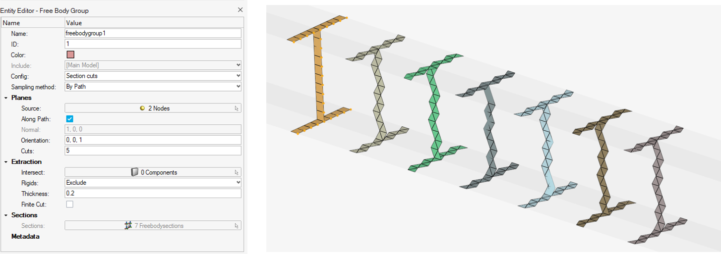
- In the Free Body Group dialog, verify Section cuts is selected for Config.
- For Sampling method, select By Path.
-
For Source, select at least two nodes to define a polyline of straight
segments.
Note: A Free Body Section will be created at each location selected for Source.
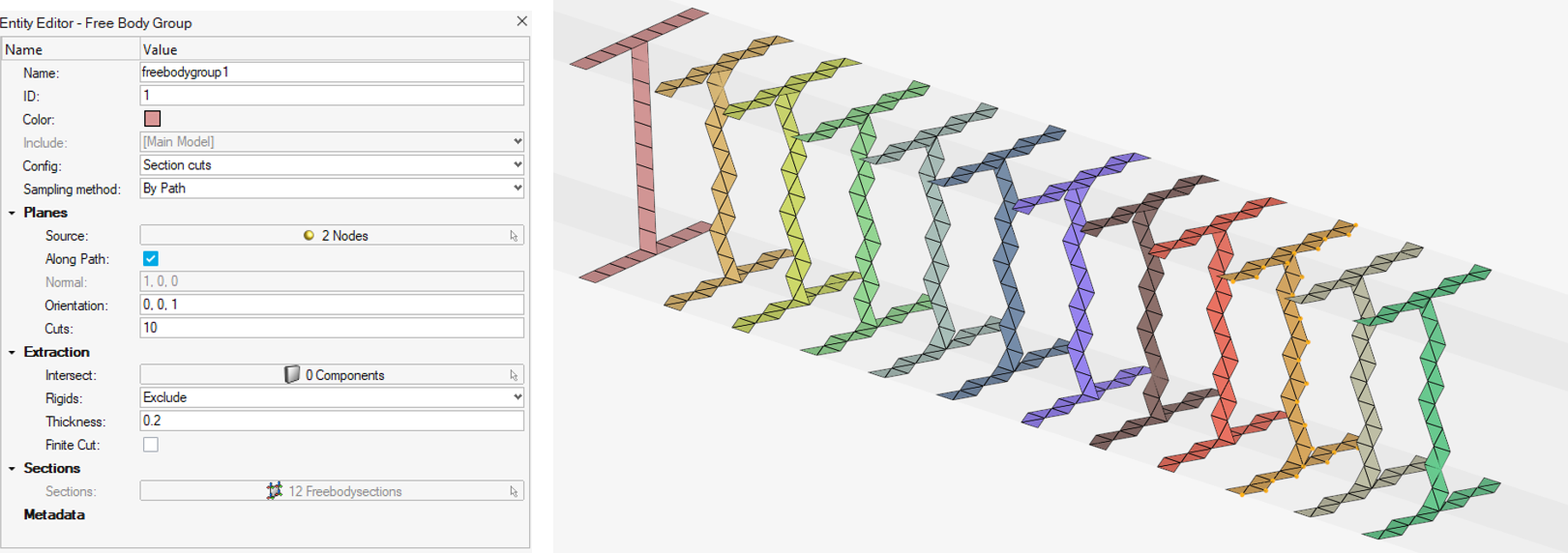
- Sample multiple sections along each segment.
- Optional: For Cuts, enter a value greater than 0 to evenly distribute intermediate planes between each node.
-
Select Normal.
The Along path option controls the normal of each Free Body Section created.
- If the option is cleared, then all Free Body Sections will share the same normal vector defined in Normal, see Figure 7.
- If the option is selected, then the following rules apply:
- Planes distributed between two consecutive nodes have their normal aligned with the direction formed by the two given nodes in ordered way.
- If a node is shared between two segments along a path, then the local normal on that node is driven by the next segment.
-
Define the Orientation.
The vector defines the system of each plane using the following rule:
- Z-axis = Normal
- Y-axis = Normal ^ Orientation
- X-axis = y-axis ^ z-axis
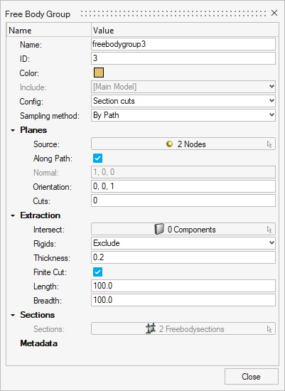
- Optional:
Select Finite cut to create Free Body Sections of finite
cut type using the Length and Breadth options.
- Length: section dimension along local x direction centered on the base point.
- Breadth: section dimension along local y direction centered on the base point.
Update Free Body Sections Along a Node Path
- A bulk update of all children entities is done without deletion, whenever possible.
- If the number of Cuts or the Source nodes are changed, then previous Free Body Sections are deleted and new entities are generated.
Generate Free Body Sections Using a System
-
From the Post ribbon, select the Create Free
Body Group tool.
Figure 10.
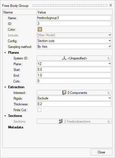
- In the Free Body Group dialog, verify Section cuts is selected for Config.
- For Sampling method, select By Axis.
- Optional:
Select a System.
Note: By default, the global system of HyperMesh is used.
-
Define a Plane.
The selection of the plane will feed Normal and Orientation datanames of all Free Body Sections using the following rules:
- XY: Normal = System z-axis and Orientation= System x-axis
- YZ: Normal = System x-axis and Orientation= System y-axis
- ZX: Normal = System y-axis and Orientation= System z-axis
- Optional:
Select Finite cut to create Free Body Sections of finite
cut type using the Length and Breadth options.
- Length: section dimension along local x direction centered on the base point.
- Breadth: section dimension along local y direction centered on the base point.
Update Free Body Sections in System
- A bulk update of all children entities is done without deletion, whenever possible.
- Changing Plane will bulk update Base, Normal, and Orientation of its children.
- If the number of Cuts is changed, then previous Free Body Sections are deleted and new entities are generated.