UTD (Polygonal and Cylindrical)
With this option the UTD parameters for UTD polygons and cylinders are specified.
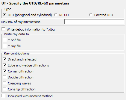
Figure 1. The UT - Specify the UTD/RL-GO parameters dialog, set to UTD (polygonal and cylindrical).
Parameters:
- Max no. of ray interactions
- This parameter gives the maximal number of ray-interactions (that is reflection and diffraction combined). If for example, the parameter is set to 3, a ray can have 3 reflections, or 2 reflections and a diffraction. If set to 0, only direct rays are taken into account.
- Write debug information to *.dbg
- If this item is checked a debug file (extension .dbg) is generated. It contains large amounts of information and should only be used when debugging.
- Write ray data to
-
- *.bof file (default)
- This option exports the rays during the UTD solution process to the .bof file for visualisation in POSTFEKO.
- *.ray file
- This option exports the rays during the UTD
solution process to a .ray file.
This text file can be used for custom post-processing.Note:
- Large .ray files are possible when the MoM and UTD solution have not been decoupled and the MoM part contains a large number of mesh elements.
- For parallel runs the run-time can also increase significantly when exporting ray data.
The following abbreviations are used in the .ray file and POSTFEKO:- ·: Creeping wave intermediate point on geometry surface
- B: Diffraction at an edge
- D: Diffraction at a corner or a tip
- K: Diffraction at a wedge
- Q: Source point
- R: Reflection
- S: Observation point
- C: Creeping wave attaching and shedding point on geometry surface
- V: Reflection at the shadow boundary of a creeping wave
- Ray contributions
- Determines which ray contributions to take into account.
- Uncoupled with moment method
- This item specifies whether the coupling from the UTD region to the MoM region should be considered. This option should only be used when the UTD and MoM regions do not couple (interact) strongly.
The following restrictions apply for the hybrid MoM/UTD:
- No dielectric bodies or dielectric ground.
- Only flat polygonal plates or a single cylinder allowed in the UTD region.
- The structure types can be PEC or of lossy metals, and the PEC structures can have coatings and thin dielectric sheets.
- UTD and PO are not allowed to be used simultaneously in a model.