MB Card
With this card, a modal port boundary condition may be applied on the boundary of a finite element method (FEM) region. A modal port essentially represents an infinitely long guided wave structure (transmission line) connected to a dielectric volume modelled with FEM.
In the Source/load tab, in the Ports group,
click the ![]() Modal boundary (MB) icon.
Modal boundary (MB) icon.
Parameters:
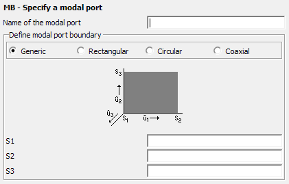
- Name of the modal port
- The label of the modal port.
- Define modal port boundary
-
- Rectangular
- A rectangular waveguide cross section is used, which is defined by three points S1, S2, and S3 as follows: S1 is an arbitrary corner point, and S2 and S3 are two corner points which define the waveguide sides (from S1 to S2) and (from S1 to S3). The direction in which the mode is launched is given by .
- Circular
- A circular waveguide cross section is used. The point S1 denotes the centre of the circular port, and the point S2 specifies the radius and start point for the angular dependency. A further point S3 must be perpendicular above the centre of the circular plate, so that the direction from S1 to S3 indicates the direction in which the waveguide modes are launched.
- Coaxial
- Here a feed of a coaxial waveguide with circular cross sections of both the inner and outer conductor can be specified. The point definitions are the same as for the circular waveguide, except that an additional point S4 must be defined between S1 and S2 which specifies the radius of the inner conductor.
- S1
- Point S1 situated on the FEM modal boundary.
- S2
- Point S2 situated on the FEM modal boundary.
- S3
- Point S3 situated on the FEM modal boundary.
Note that the modal port is only available in conjunction with FEM applied to dielectrics. A FEM modal port can only be applied on the boundary of a FEM dielectric region, situated on a planar surface.
The technology behind a modal port is a two dimensional FEM eigensolver that computes the eigenvalues (modal propagation constants) and eigenvectors (modal electric field distribution) for the associated infinitely long guided wave structure.
The memory requirement can, for a modal port, be estimated from the number of tetrahedral faces on the modal port and the order of the solution. The eigensolver by default uses second order basis functions. Changing the solver settings to use first order basis functions for the FEM (FP card) will also apply to the modal port analysis. The number of unknowns for a first order solution is roughly double the number of modal port triangles, and for a second order solution, 7 times the number of modal port triangles. The memory requirement scales with N2, where N is the number of unknowns.
The user should take note that memory and runtime scaling could become an issue with finely meshed modal port geometries. Note that when meshing modal ports, the default is to use second order basis functions on modal ports. Hence, a coarser mesh can be used than on the FEM/MoM boundary (where first order basis functions are always used).