Faceted UTD
With this option the UTD parameters for faceted UTD for planar and curved faces are specified.
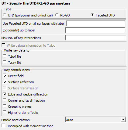
Figure 1. The UT - Specify the UTD/RL-GO parameters dialog, set to Faceted UTD.
Parameters:
- Use faceted UTD on all surfaces with label
- The label to which the faceted UTD should be applied
- (optionally) up to label
- The label up to which the faceted UTD should be applied. Faceted UTD will not be applied to labels outside of the range between this field and the label in the previous field.
- Max no. of ray interactions
- This parameter gives the maximal number of ray-interactions. If for example, the parameter is set to 3, a ray can have 3 reflections. If set to 0, only direct rays are taken into account.
- Write ray data to
-
- *.bof file (default)
- This option exports the rays during the UTD solution process to the .bof file for visualisation in POSTFEKO.
- *.ray file
- This option exports the rays during the UTD
solution process to a .ray file.
This text file can be used for custom post-processing.Note:
- Large .ray files are possible when the MoM and UTD solution have not been decoupled and the MoM part contains a large number of mesh elements.
- For parallel runs the run-time can also increase significantly when exporting ray data.
The following abbreviations are used in the .ray file and POSTFEKO:- ·: Creeping wave intermediate point on geometry surface
- B: Diffraction at an edge
- D: Diffraction at a corner or a tip
- K: Diffraction at a wedge
- Q: Source point
- R: Reflection
- S: Observation point
- C: Creeping wave attaching and shedding point on geometry surface
- V: Reflection at the shadow boundary of a creeping wave
- Ray contributions
- Determines which ray contributions to take into account.
- Uncoupled with moment method
- This item specifies whether the coupling from the faceted UTD region to the MoM region should be considered. This option should only be used when the faceted UTD and MoM regions do not couple (interact) strongly.
- Enable acceleration
-
An acceleration technique can be used to speed-up the search process for ray paths significantly but could result in some rays not being found in exceptional cases.
- Auto
- The Solver determines automatically if the acceleration technique should be used for the model (if the method is likely to speed up the solution).
- On
- This option enables the acceleration technique. Runtime decreases but technique could result in some rays not being found in exceptional cases.
- Off
- This option disables the acceleration technique at the expense of a runtime increase.
The following restrictions apply for the faceted UTD:
- Only PEC structures are allowed (no dielectric bodies, thin dielectric sheets or coatings are allowed).
- Only planar triangles are allowed.