Magnetic Field
![]()
Introduction
The Magnetic Field allows to define the boundary conditions of the magnetic field direction which can be tangential or normal.
It can be used instead of the Infinite Box Load and Constraint by creating an air bounding box around the studied device and assigning the external faces to the Magnetic Field Load and Constraint with the correct magnetic field direction.
- 3D Magnetostatic
- 3D Transient Magnetic
- 3D AC Magnetic
Dialog Box
The Magnetic Field Load and Constraint is available in the More tools ribbon:
The Magnetic Field Load and Constraint dialog is as following:
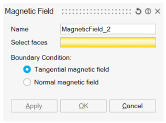
- Select the faces to apply the Boundary Condition on the magnetic field direction
- Select Tangential magnetic field or Normal
magnetic field
In 3D solutions, when applying the Magnetic Field Boundary Condition on the external air bounding box, it is recommended to select Tangential magnetic field.
Steps to define the air bounding box
- CAD bounding box around CAD bodies
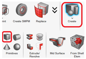
- Create a CAD Box around the device CAD bodies
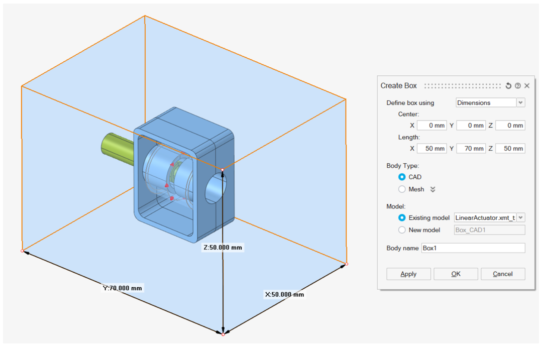
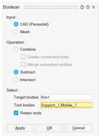
- Do a Boolean
Subtract by selecting the bounding box as
Target bodies and the device bodies as
Tool bodies:
- Create a CAD Box around the device CAD bodies
- Meshed bounding box around surface or volume meshed bodies
- Create a Surface meshed bounding box body around the device meshed bodies
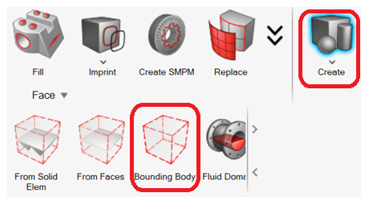
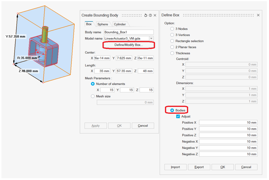
- Click on Define/Modify Box...
- Select Bodies, select the device bodies and enter the positive and negative X / Y / Z shift. Click on OK
- Select the bounding box mesh inputs
- Tet Mesh the bounding box by selecting the bounding box body and the device bodies in order to have a conform mesh
- Create a Surface meshed bounding box body around the device meshed bodies