Thin Region

Introduction
The Thin Region Load and Constraint enables modeling bodies with a small thickness.
It simplifies the model set-up, especially the meshing.
The meshing and solving processes are executed more efficiently and rapidly.
Thin Region types and inputs
In 3D Electrostatic, only one type of Thin Region is available: Dielectric Thin Region:

First of all, Thin Region name is entered, and faces defining the Thin Region are selected.
- Enter a thickness value
- Assign a material with Dielectric Class (DE curve)
- Define the boundary condition with electric field direction (Almost tangent / no restriction)
- Optional: Enter the electric charge either in a total value or in a volume density value
Post processing on the Thin Region
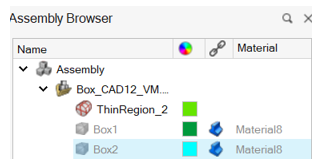
At the end of solving, a shell body associated to each Thin Region is automatically created to allow the post processing on it. The Shell body name corresponds to the Thin Region name.
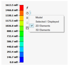
In order to see Contour/Vectors on the Thin Region shell body:
-
Display the shell body and hide the solid bodies in contact with it
- Select the following option: 2D
Elements