Connected Pattern Direction
Check the pattern opposite routed directions.
In the manufacturing process, if heat is applied to the patterns, they will be
contracted or expanded and result in component misalignment. Check this item to
prevent this malfunction.
- Checking
- Check Pattern Direction: Check the pattern direction.
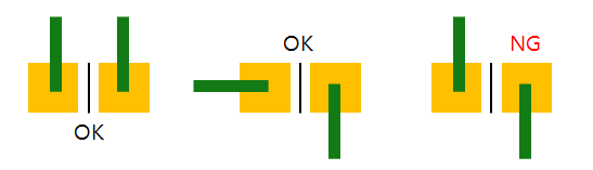
Figure 1.- Target Component Definition: Define target components.
- All SMD Components having 2 Pins: Include all SMD type 2 pin components in the target components list.
- Component Group Selection: Select target components from the component group list.
- Target Object Definition: Define target objects.
- Trace: Target components connecting routing patterns will be target objects.
- Copper: Target components connecting copper-pour will be target objects.
- Exclude Minimum Ratio of Width for Pattern Width to Pad
Width (Pattern Width x 100/ Pad Width): For certain patterns
connected to pad will not be checked. Thinner patterns than
the given ratio will be excluded in checking.
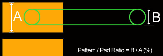
Figure 2.
- Target Component Definition: Define target components.
- Check Similar connected Pattern’s Width for each Pad: Check patterns
which have similar patterns with pad in width.
- Target Component Definition: Define target components.
- All SMD Components having 2 Pins: Include all SMD type 2 pin components in the target components list.
- Component Group Selection: Select target components from the component group list.
- Target Object Definition: Define target objects.
- Trace: Target components connecting routing patterns will be target objects.
- Copper: Target components connecting copper-pour will be target objects.
- Allowable Ranges of Comparing Ratio for 2 Connections:
Define allowable range (%) for the connected width compared
to the other side. Difference ratio of copper connection
width: (0.2/(0.4*3))*100 = 16.666%)
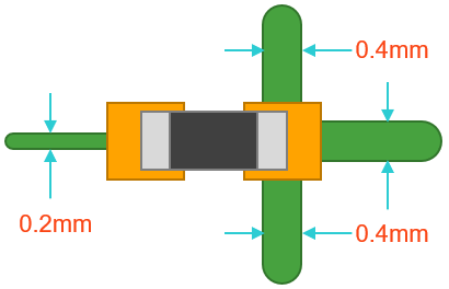
Figure 3. - Excluding Net Name Filters: For nets with specifying character string in the name will not be checked.
- Target Component Definition: Define target components.
- Check the right angled Pattern from Pad Edge: Check pad connected
patterns are connected with an angle of 90 degree.
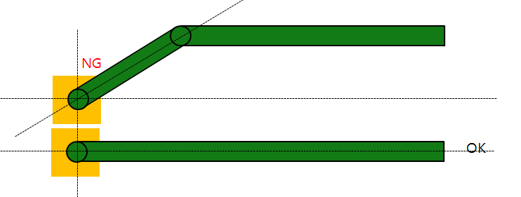
Figure 4.- All Components: All components will be target components.
- Component Group Selection: Select target components from the component group list.
- Allow diagonal patterns on the pad corner(only applicable for the rectangle-type pad): Diagonal patterns through the edges of the pad are allowed.
- Keeping a straight the line within a given distance from the
Pad: Check pad connected patterns keep 90 degree within the
given distance.
- When this option is checked, the diagonal pattern passing through the edge of the pad is also subject to checking under the Keeping a straight line within a given distance from the Pad option below.
-
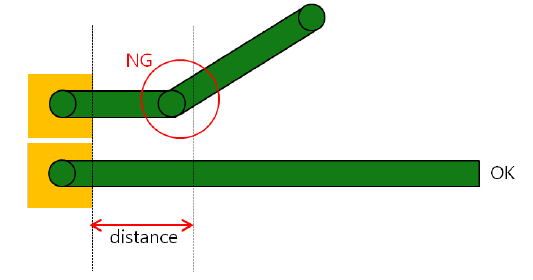
Figure 5. - Check the Pattern connected with Pad's short side: Check if
patterns connected to pads with length-width asymmetry are
connected through the shorter side
- All Components: All components will be target components.
- Component Group Selection: Select target components from the component group list.
- Check Pattern Direction: Check the pattern direction.