
RD-E: 2202 Ditching using SPH
The ditching of an object into a pool of water is studied.
The simulation results are compared to the experimental data and the analytical results. The ditching object is modeled as a rigid prism. The water is modeled using SPH elements with an outlet condition to allow for a non-reflecting boundary condition.
Options and Keywords Used
- SPH modeling
- Hydrodynamic viscous fluid law (/MAT/LAW6 (HYDRO or HYD_VISC)) and impact on water modeling
- Interface /INTER/TYPE7
- Rigid body (/RBODY)
- Initial velocity (/INIVEL)
- Accelerometer (/ACCEL)
- Gravity (/GRAV)
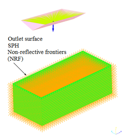
- SPH outlet (/SPH/INOUT)
- Parameter input (/PARAMETER)
Input Files
Model Description
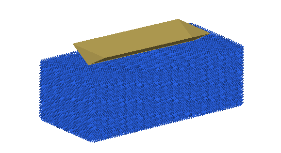
The problem consists of a simple object falling into water simulating the ditching of a helicopter.
Units: mm, ms, KN, GPa, kg.
- Material Properties
- Value
- Initial density
- 7.8 x 10⁻⁶ kg.mm-3
- Young's modulus
- 206.9 GPa
- Poisson's ratio
- 0.3
- Material Properties
- Value
- Initial density
- 1 x 10⁻⁶ kg.mm-3
- Kinematic viscosity
- 0 GPa
- Gamma
- 6.1
- P0
- 1e-4 GPa
- Psh
- 0 GPa
- p*
- 0.36885 GPa
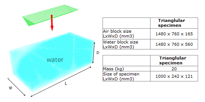
The impacting prism is modeled using shell elements with an average mesh size of 15 mm x 15 mm. To shorten the computation, it is made rigid with an accelerometer on the main node of the rigid body. Additional mass is added to the main node of the rigid body, so the total mass of the prism is 27 kg.
The water is modeled using SPH particles with a face-centered cubic mesh and smoothing length "ho" equal to 21 mm. Each SPH weighs m=2.61 g. The SPH particle mesh can be generated in HyperMesh using the SPH panel with a face-centered cubic pitch=15, and a material density of 1.0e-6 . HyperMesh will then automatically create SPH property /PROP/SPH. This results in 222005 SPH elements. The size of the water is adapted to the shape of the object to reduce the model’s size and the simulation’s CPU time. For an SPH analysis, air is not typically modeled.
Boundary Setup
An initial velocity of 11 m/s in the Z direction is defined on the main node of the rigid body of the prism. Gravity is also applied to the prism.
The fluid-structure contact between the impacting prism and SPH water is modeled using a /INTER/TYPE7 sliding penalty contact interface. The impacting prism is the main surface and the SPH elements are the secondary nodes. The contact thickness gap is defined as Gapmin=3. For situations when the contact thickness gap is important such as when the SPH particles are in a tank, define Gapmin=1/2 * (shell thickness + SPH diameter) or for solid elements Gapmin=1/2 * (SPH diameter).
Results
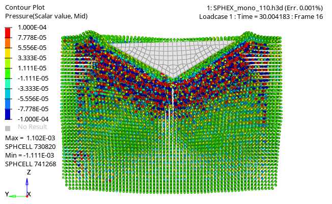
The SPH particles are supported as MASS elements in HyperView. Their display type and size can be set in HyperView by using . In this example, the animation results are directly output to an h3d file using the /H3D option. The pressure in the water can be plotted.
Output Acceleration
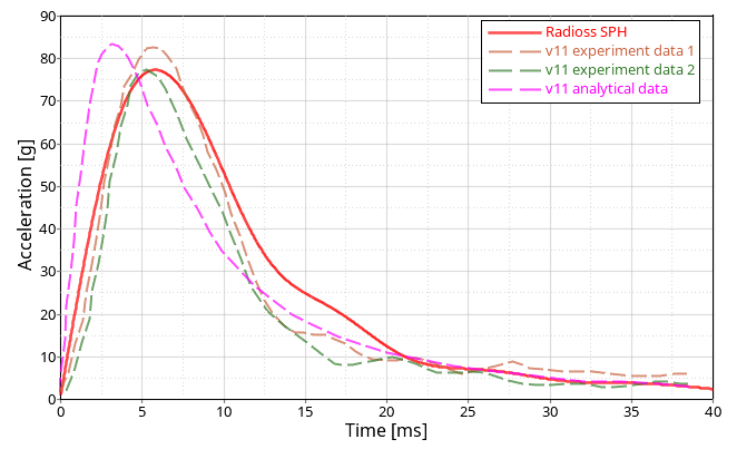
The SPH results are very close to the experimental test results and also to the analytical solution. The simulations show that the SPH approach using the OUTLET option /SPH/INOUT correctly models a vertical ditching event without any numerical problems.