RD-E: 5000 INIVOL and Fluid Structure Interaction (Drop Container)
The aim of this example is to introduce /INIVOL for initial volume fractions of different materials in multi-material ALE elements, /SURF/PLANE for infinite plane, and fluid structure interaction (FSI) with a Lagrange container.
Options and Keywords Used
- Solid element (/BRICK)
- Material laws (/MAT/LAW51 (MULTIMAT) and /MAT/LAW6 (HYDRO or HYD_VISC))
- Property (/PROP/TYPE14 (SOLID) with ALE property formulation Iale = 1)
- Load (/INIVEL)
- Define initial volume (/INIVOL)
- Infinite surface plane (/SURF/PLANE)
- Fluid structure contact (/INTER/TYPE18)
Input Files
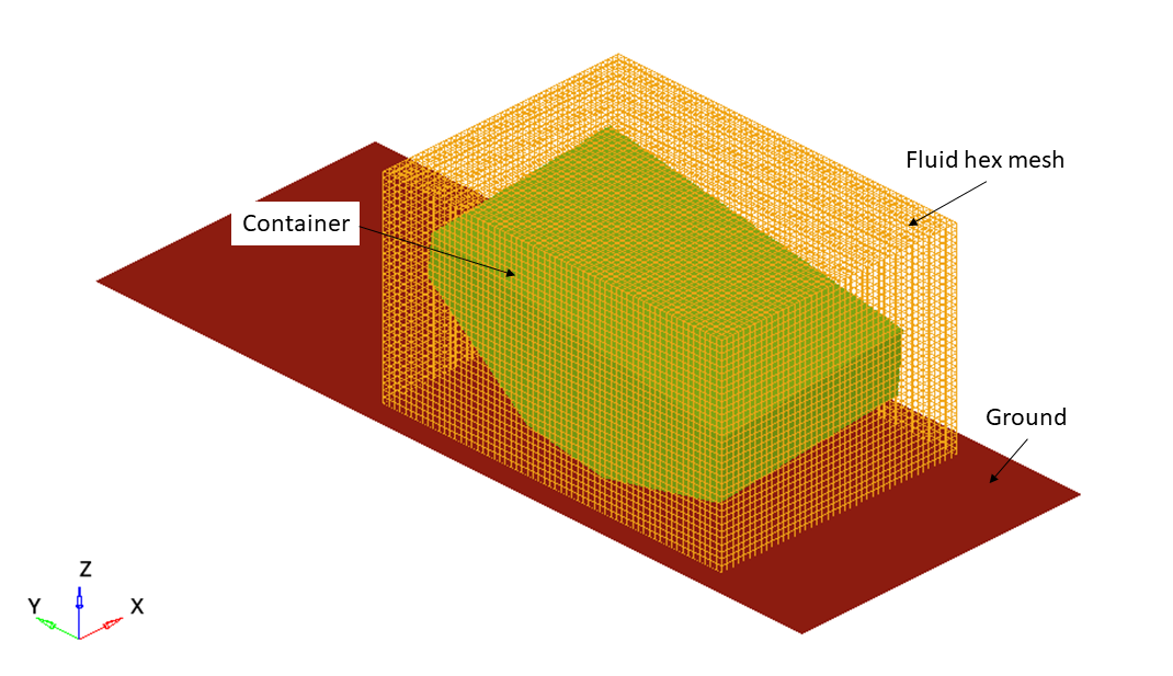
Model Description
A hex mesh is created that fully encloses the structural container. The mesh size of the hex mesh should be ½ the size of the structural mesh. Ideally the hex mesh should also be ¼ of the structural mesh size in the direction of impact. To simplify this example, the hex mesh in this model does not adhere to the ¼ mesh size guideline.
Boundary Conditions
Units: mm, s, Mg, N, MPa
In a /MAT/LAW51 card, three different phases can be defined. The two phases are: Air and Water
- EoS_Options_input (IDEAL_GAS)
- Value
- Reference density
- 1.22e-12
- Initial density
- 1.22e-12
- Heat Capacity Ration (Gamma)
- 1.4
- Initial Pressure (P0)
- 0.1
- EoS_Options_Input (LINEAR)
- Value
- Initial density
- 1e-9
- Initial Pressure (P0)
- 0.1013
- Bulk Modulus (B)
- 2089.0
Coupled Euler_Lagrange (CEL) Interface
- Main is the Lagrange structure
- Secondary is the ALE fluid nodes
Gap is the Interface gap. The recommended value is 1.5 times fluid element size along the normal direction to contact.
The contact stiffness is calculated as:
- The (highest) fluid density
- Velocity.
- For incompressible models (ditching, sloshing, and so on), use the velocity of the event.
- For compressible but not supersonic, use the speed of the sound in the material.
- Compressible and transonic (Mach 0.8 to 1.0), replace the term
with
Where,
- Speed of the sound in the material
- Speed of sound in air
- Compressible and supersonic, use the velocity of the event
- For an explosion, use the Chapman Jouguet velocity
- Surface area of the Lagrangian elements
- Interface gap, as defined above
For this example:
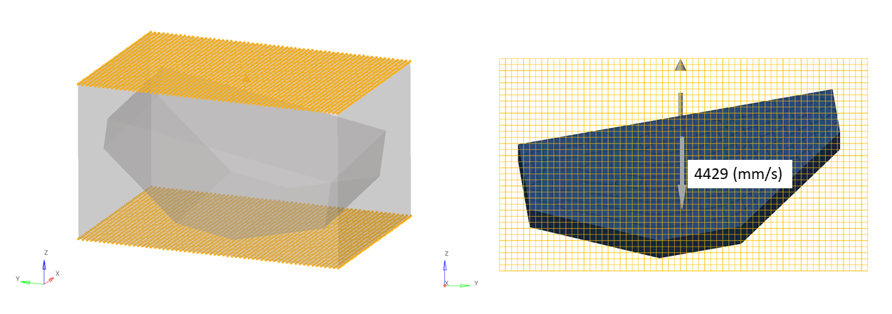
Simulation Iterations and Modeling
With /INIVOL, the water line can be defined in this part.
| (1) | (2) | (3) | (4) | (5) | (6) | (7) | (8) | (9) | (10) |
|---|---|---|---|---|---|---|---|---|---|
| /INIVOL/part_ID/inivol_ID | |||||||||
| inivol_title | |||||||||
| surf_ID | ALE_PHASE | FILL_OPT | ICUMU | FILL_RATIO | |||||
| surf_ID | ALE_PHASE | FILL_OPT | ICUMU | FILL_RATIO | |||||
| etc | etc | etc | etc | etc | |||||
| surf_IDn | ALE_PHASE | FILL_OPT | ICUMU | FILL_RATIO | |||||
- part_ID
- Part ID of ALE hex mesh
- surf_IDn
- 3-nodes or 4-nodes surfaces only or /SURF/PLANE
- ALE_PHASE
- Phase of the multi-material ALE material
- FILL_OPT
-
- = 0
- Filling the side which along normal direction
- = 1
- Filling the side which against normal direction
Figure 3. 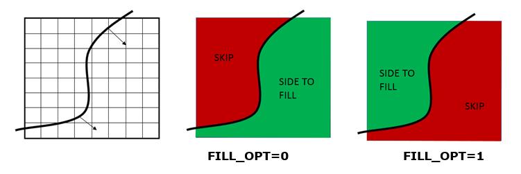
- ICUMU
- Remove the previous material and then fill new material or mixed
- FILL_RATIO
- Ratio of filling material
/SURF/PART/998
Vessel_Surf_Part
85/INIVOL/86/10003507
INIVOL
# Surf_ID ALE_PHASE FILL_OPT ICUMU FILL_RATIO
998 2 1 0 0.0# Surf_ID ALE_PHASE FILL_OPT ICUMU FILL_RATIO
9999 1 0 0 0.0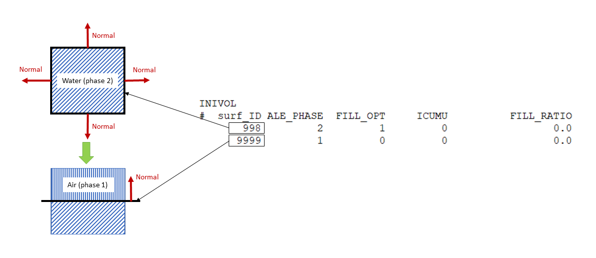
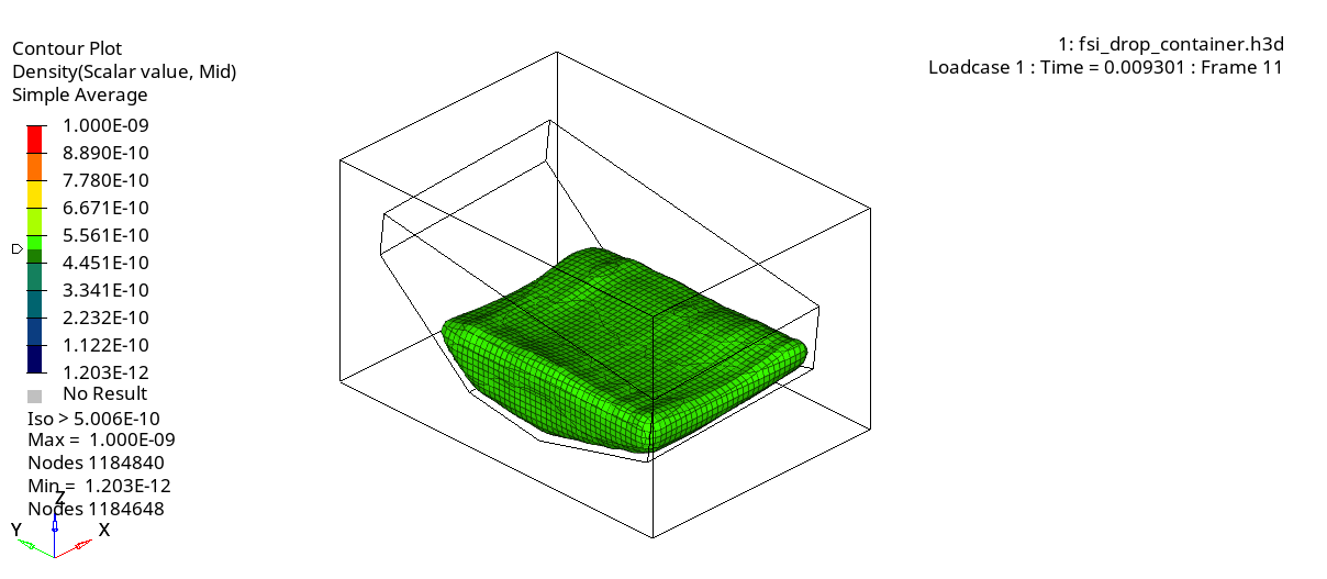
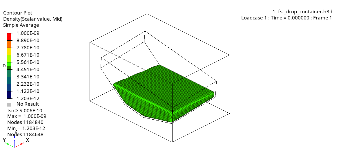
- /H3D/ELEM/DENS
- /H3DE/ELEM/VFRAC
You can contour the model and use section cut to see inside, or use iso-surface, as shown in Figure 5.
Engine Control
It is recommended to use time step scale factor 0.5 for ALE in /DT/ALE in order to keep computation stable.
Results
To see the movement of the water in the container, and iso-surface plot of results type "density” can be done. If the simple averaging method is used in HyperView, the results will look smoother.