RD-E: 1000 Bending

Pure bending test with different 3- and 4-nodes shell formulations.

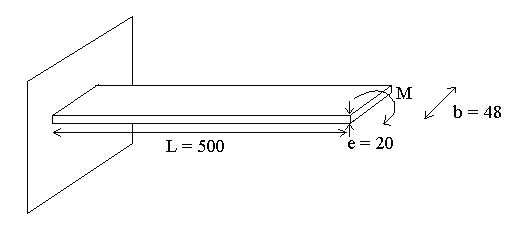
The bending of a straight cantilever beam is studied. The example used is a famous bending test for shell elements. The analytical solution enables the comparison with the quality of the numerical results. Carefully watch the influence from the shell formulation. In addition, the results for the different time step scale factors are compared.
Figure 1.

rad_ex_10_bending

Options and Keywords Used

  • Q4 and T3 meshes
  • QEPH, Belytshcko & Tsay, BATOZ, and DKT shells
  • Mesh, hourglass, quasi-static analysis, and bending test
  • Imposed velocity (/IMPVEL)
  • Rigid bodies (/RBODY)

At one extremity of the beam, all DOF are blocked. A rotational velocity is imposed on the main node of the rigid body placed on the other side.
This velocity follows a linear function: Y=1
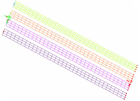
Figure 2. Beam Meshes

rad_ex_fig_10-2

Input Files

Before you begin, copy the file(s) used in this example to your working directory.

Model Description

The purpose of this example is to study a pure bending problem. A cantilever beam with an end moment is studied. The moment variation is modeled by introducing a constant imposed velocity on the free end.

The following system is used: mm, ms, g, N, MPa

Several kinds of element formulation are used.

The material used follows a linear elastic law (/MAT/LAW1) with the following characteristics:
Material Properties
Value
Initial density
0.01 [ g m m 3 ] MathType@MTEF@5@5@+= feaagKart1ev2aaatCvAUfeBSjuyZL2yd9gzLbvyNv2CaerbuLwBLn hiov2DGi1BTfMBaeXatLxBI9gBaerbd9wDYLwzYbItLDharqqtubsr 4rNCHbGeaGqiVu0Je9sqqrpepC0xbbL8F4rqqrFfpeea0xe9Lq=Jc9 vqaqpepm0xbba9pwe9Q8fs0=yqaqpepae9pg0FirpepeKkFr0xfr=x fr=xb9adbaqaaeGaciGaaiaabeqaamaabaabaaGcbaWaamWaaeaada WcaaqaaiaadEgaaeaacaWGTbGaamyBamaaCaaaleqabaGaaG4maaaa aaaakiaawUfacaGLDbaaaaa@3BBC@
Reference density
.01 [ g m m 3 ] MathType@MTEF@5@5@+= feaagKart1ev2aaatCvAUfeBSjuyZL2yd9gzLbvyNv2CaerbuLwBLn hiov2DGi1BTfMBaeXatLxBI9gBaerbd9wDYLwzYbItLDharqqtubsr 4rNCHbGeaGqiVu0Je9sqqrpepC0xbbL8F4rqqrFfpeea0xe9Lq=Jc9 vqaqpepm0xbba9pwe9Q8fs0=yqaqpepae9pg0FirpepeKkFr0xfr=x fr=xb9adbaqaaeGaciGaaiaabeqaamaabaabaaGcbaWaamWaaeaada WcaaqaaiaadEgaaeaacaWGTbGaamyBamaaCaaaleqabaGaaG4maaaa aaaakiaawUfacaGLDbaaaaa@3BBC@
Young's modulus
1000 [ MPa ] MathType@MTEF@5@5@+= feaagKart1ev2aqatCvAUfeBSjuyZL2yd9gzLbvyNv2CaerbuLwBLn hiov2DGi1BTfMBaeXatLxBI9gBaerbd9wDYLwzYbItLDharqqtubsr 4rNCHbGeaGqiVu0Je9sqqrpepC0xbbL8F4rqGqFfpeea0xe9vq=Jb9 vqpeea0xd9q8qiYRWxGi6xij=hbba9q8aq0=yq=He9q8qiLsFr0=vr 0=vr0db8meaabaqaciGacaGaaeqabaWaaeaaeaaakeaadaWadaqaai Gac2eacaGGqbGaaiyyaaGaay5waiaaw2faaaaa@3BE6@
Poisson ratio
0
Figure 3. Geometry of the Problem

rad_ex_fig_10-1

Model Method

The four models are integrated into one input file. The shell element formulations are:
  • Q4 mesh with the Belytshcko & Tsay formulation (Ishell =1, hourglass control TYPE1, TYPE2, and TYPE3)
  • Q4 mesh with the QEPH formulation (Ishell =24)
  • Q4 mesh with the QBAT formulation (Ishell =12)
  • T3 mesh with the DKT18 formulation (Ishell =12)

Results

Numerical Results and Analytical Solution Comparison

As shown in Figure 3, rotation around X and displacement with regard to Y of the free end are studied.

The analytical solution of the Timoshenko beam subjected to a tip moment reads:

θ( z )= Mz EI MathType@MTEF@5@5@+= feaagKart1ev2aaatCvAUfeBSjuyZL2yd9gzLbvyNv2CaerbuLwBLn hiov2DGi1BTfMBaeXatLxBI9gBaerbd9wDYLwzYbItLDharqqtubsr 4rNCHbGeaGqiVu0Je9sqqrpepC0xbbL8F4rqqrFfpeea0xe9Lq=Jc9 vqaqpepm0xbba9pwe9Q8fs0=yqaqpepae9pg0FirpepeKkFr0xfr=x fr=xb9adbaqaaeGaciGaaiaabeqaamaabaabaaGcbaGaeqiUde3aae WaaeaacaWG6baacaGLOaGaayzkaaGaeyypa0ZaaSaaaeaacaWGnbGa amOEaaqaaiaadweacaWGjbaaaaaa@3EB3@

Which yields the end moment for a complete loop rotation 2 π MathType@MTEF@5@5@+= feaagKart1ev2aaatCvAUfeBSjuyZL2yd9gzLbvyNv2CaerbwvMCKf MBHbqefqvATv2CG4uz3bIuV1wyUbqedmvETj2BSbqefm0B1jxALjhi ov2DaebbnrfifHhDYfgasaacH8srps0lbbf9q8WrFfeuY=Hhbbf9v8 qqaqFr0xc9pk0xbba9q8WqFfea0=yr0RYxir=Jbba9q8aq0=yq=He9 q8qqQ8frFve9Fve9Ff0dmeaacaGacmGadaWaaiqacaabaiaafaaake aacaaIYaGaeqiWdahaaa@3B50@ :

M = 2 π E I L = 2 π ( 1000 ) ( 48 * 20 3 12 ) 500 = 4.021 × 10 5 KN-mm MathType@MTEF@5@5@+= feaagKart1ev2aaatCvAUfeBSjuyZL2yd9gzLbvyNv2CaerbuLwBLn hiov2DGi1BTfMBaeXatLxBI9gBaerbd9wDYLwzYbItLDharqqtubsr 4rNCHbGeaGqiVu0Je9sqqrpepC0xbbL8F4rqqrFfpeea0xe9Lq=Jc9 vqaqpepm0xbba9pwe9Q8fs0=yqaqpepae9pg0FirpepeKkFr0xfr=x fr=xb9adbaqaaeGaciGaaiaabeqaamaabaabaaGcbaGaamytaiabg2 da9maalaaabaGaaGOmaiabec8aWjaadweacaWGjbaabaGaamitaaaa cqGH9aqpdaWcaaqaaiaaikdacqaHapaCdaqadaqaaiaaigdacaaIWa GaaGimaiaaicdaaiaawIcacaGLPaaadaqadaqaamaalaaabaGaaGin aiaaiIdacaGGQaGaaGOmaiaaicdadaahaaWcbeqaaiaaiodaaaaake aacaaIXaGaaGOmaaaaaiaawIcacaGLPaaaaeaacaaI1aGaaGimaiaa icdaaaGaeyypa0JaaGinaiaac6cacaaIWaGaaGOmaiaaigdacqGHxd aTcaaIXaGaaGimamaaCaaaleqabaGaaGynaaaakiaaygW7caaMe8Ua ae4saiaab6eacaqGTaGaaeyBaiaab2gaaaa@5F0B@

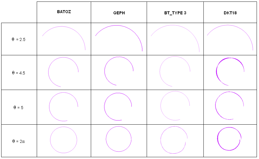
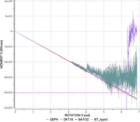
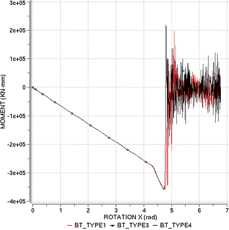
The following tables summarize the results obtained for the different formulations. From an analytical point of view, the beam deformed under pure bending must satisfy the conditions of the constant curvature which implies that for θ = 2 π MathType@MTEF@5@5@+= feaagKart1ev2aaatCvAUfeBSjuyZL2yd9gzLbvyNv2CaerbwvMCKf MBHbqefqvATv2CG4uz3bIuV1wyUbqedmvETj2BSbqefm0B1jxALjhi ov2DaebbnrfifHhDYfgasaacH8srps0lbbf9q8WrFfeuY=Hhbbf9v8 qqaqFr0xc9pk0xbba9q8WqFfea0=yr0RYxir=Jbba9q8aq0=yq=He9 q8qqQ8frFve9Fve9Ff0dmeaacaGacmGadaWaaiqacaabaiaafaaake aacaaIYaGaeqiWdahaaa@3B50@ , the beam should form a closed ring. However, depending on the finite element used, a small error can be observed, as shown in the following tables. This is mainly due to beam vibration during deformation as it is highly flexible. Good results are obtained by the QBAT, QEPH and DKT18 elements, respectively. This is mainly due to the good estimation of the curvature in the formulation of these elements. The BT family of under-integrated shell elements is less accurate. With the TYE3 hourglass formulation, the model remains stable until θ = 6rad. However, the moment-rotation curves do not correspond to the expected response.

To reduce the overall computation error, smaller explicit time steps are used by reducing the scale factor in /DT. The results reported in the end table show that a reduction in the time step enables to reduce the error accumulation, even though the divergence problems for BT elements cannot be avoided.

The following parameters are chosen for drawing curves and displaying animations:
BATOZ QEPH BT DKT
Scale factor 0.6 0.9 0.9 0.2
Imposed velocity rot. 0.005 rad/ms 0.005 rad/ms 0.005 rad/ms 0.005 rad/ms
Figure 4.

rad_ex_10_table1
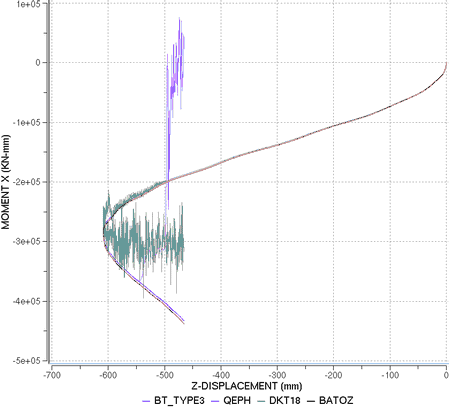
The following curves show the evolution previously shown (rotation and nodal displacement by moment):
Figure 5. Moment versus Rotation Around X
rad_ex_fig_10-4
For θ=2π M Analytical =4.021× 10 5 MathType@MTEF@5@5@+= feaagKart1ev2aaatCvAUfeBSjuyZL2yd9gzLbvyNv2CaerbuLwBLn hiov2DGi1BTfMBaeXatLxBI9gBaerbd9wDYLwzYbItLDharqqtubsr 4rNCHbGeaGqiVu0Je9sqqrpepC0xbbL8F4rqqrFfpeea0xe9Lq=Jc9 vqaqpepm0xbba9pwe9Q8fs0=yqaqpepae9pg0FirpepeKkFr0xfr=x fr=xb9adbaqaaeGaciGaaiaabeqaamaabaabaaGcbaGaeqiUdeNaey ypa0JaaGOmaiabec8aWjabgwMiZkaad2eadaWgaaWcbaGaamyqaiaa d6gacaWGHbGaamiBaiaadMhacaWG0bGaamyAaiaadogacaWGHbGaam iBaaqabaGccqGH9aqpcqGHsislcaaI0aGaaiOlaiaaicdacaaIYaGa aGymaiabgEna0kaaigdacaaIWaWaaWbaaSqabeaacaaI1aaaaaaa@5139@
Figure 6. Moment versus Displacement Along Z
rad_ex_fig_10-5
Figure 7. Moment versus Rotation Around X

rad_ex_fig_10-6_zoom67
BATOZ QEPH BT DKT
Sf=0.9 Sf =0.8 Sf =0.6 Sf =0.9 Sf =0.8 TYPE1 TYPE3 TYPE4 Sf =0.3 Sf =0.2 Sf =0.1
Sf =0.9 Sf =0.1 Sf =0.9 Sf =0.1 Sf =0.9 Sf =0.1
CPU

(normalized)

# cycles

2.18

97600

2.43

109800

3.14

146400

1.23

95800

1.34

107800

42.64

59100

7.07

552600

2.62

182300

108.60

--

1.03

59100

7.17

552600

5.44

364100

8.21

621600

16.21

1243200

Error

θ = 2 π MathType@MTEF@5@5@+= feaagKart1ev2aaatCvAUfeBSjuyZL2yd9gzLbvyNv2CaerbuLwBLn hiov2DGi1BTfMBaeXatLxBI9gBaerbd9wDYLwzYbItLDharqqtubsr 4rNCHbGeaGqiVu0Je9sqqrpepC0xbbL8F4rqqrFfpeea0xe9Lq=Jc9 vqaqpepm0xbba9pwe9Q8fs0=yqaqpepae9pg0FirpepeKkFr0xfr=x fr=xb9adbaqaaeGaciGaaiaabeqaamaabaabaaGcbaGaeqiWdahaaa@37B3@

(%)

0% 0% 0% 0% 0% 55.3% 99% 0% 0% 55.9% 99.9% 3.4% 28.88% 3.7%
θ err =20%

(rad)

degree

6.91

396°

6.89

395°

-- -- -- 4.36

250°

4.53

260°

6.06

347°

5.98

343°

4.38

251°

4.51

258°

6.37

365°

-- --
Dz θ = 2 π MathType@MTEF@5@5@+= feaagKart1ev2aaatCvAUfeBSjuyZL2yd9gzLbvyNv2CaerbuLwBLn hiov2DGi1BTfMBaeXatLxBI9gBaerbd9wDYLwzYbItLDharqqtubsr 4rNCHbGeaGqiVu0Je9sqqrpepC0xbbL8F4rqqrFfpeea0xe9Lq=Jc9 vqaqpepm0xbba9pwe9Q8fs0=yqaqpepae9pg0FirpepeKkFr0xfr=x fr=xb9adbaqaaeGaciGaaiaabeqaamaabaabaaGcbaGaeqiWdahaaa@37B3@

(mm)

-500.5 -500.5 -500.5 -500.5 -500.5 -491.2 -525.8 -518.333 -506.0 -529.8 -433.8 -476.5 -496.5 -499.4
Mx θ = 2 π MathType@MTEF@5@5@+= feaagKart1ev2aaatCvAUfeBSjuyZL2yd9gzLbvyNv2CaerbuLwBLn hiov2DGi1BTfMBaeXatLxBI9gBaerbd9wDYLwzYbItLDharqqtubsr 4rNCHbGeaGqiVu0Je9sqqrpepC0xbbL8F4rqqrFfpeea0xe9Lq=Jc9 vqaqpepm0xbba9pwe9Q8fs0=yqaqpepae9pg0FirpepeKkFr0xfr=x fr=xb9adbaqaaeGaciGaaiaabeqaamaabaabaaGcbaGaeqiWdahaaa@37B3@

(x10+5kN-mm)

-4.04 -4.05 -4.06 -4.01 -4.01 -0.21 -0.11 -3.13 -2.38 -0.07 -0.02 -3.09 -3.02

-3.08

Conclusion