RD-E: 2300 Brake
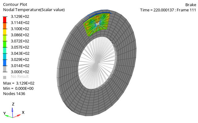
A frictional mechanism is studied, which consists of a brake system, defined by a disc pinched between two pads.
Options and Keywords Used
- /BRICK elements
- /MAT/LAW2 (PLAS_JOHNS) (Isotropic elasto-plastic material using the Johnson-Cook material model)
- /INTER/TYPE19 (Multi-usage impact interface; consideration of heat transfer and heat friction is possible)
- /HEAT/MAT (Describes thermal parameters for thermal analysis)
- /PROP/TYPE14 (SOLID) (Defines the general solid property set)
- /BCS (Boundary condition)
- /INIVEL/AXIS (Initialize both translational and rotational velocities on a group of nodes in a given coordinate system)
- /CLOAD (Defines a concentrated force or moment applied to each node of a prescribed nodal group)
Input Files
Model Description
The objective of this example is to demonstrate the simulation of a friction mechanism using Altair Radioss.
Units: kg, mm, ms, GPa
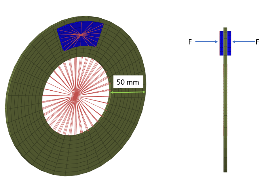
The brake system consists of a disc with a radius of 100 mm, a width of 50 mm, a thickness of 5 mm, and mass = 0.914 kg clamped between two brake pads which are 5 mm thick and weigh 0.06 kg each. The parts are modeled using brick elements using the HEPH (Isolid=24) element formulation.
The disc has an initial rotational velocity of . The initial rotational velocity is defined using the /INIVEL/AXIS keyword. This results in an inertia of 5712.5 kg/mm2. A rigid body is created within the inner diameter of the disc. The main node of this rigid body is the center of the rotation and is constrained in all DOFs, except rotation around Y-axis.
A rigid body is created on the outside face of each brake pad. To simulate braking, a concentrated force of 0.3 kN is applied to the main node of each rigid body attached to the two pads. The pads then contact each side of the disc.
The material model used for the disc and pad is an isotropic elasto-plastic law (/MAT/LAW2) using the Johnson-Cook plasticity model. To model heat transfer between the disc and pad, thermal parameters for the material must be defined in /HEAT/MAT and use the same mat_ID as the /MAT/LAW2 material. When /HEAT/MAT is used with a material, the parameters entered in /HEAT/MAT are used, instead of the thermal parameters in /MAT/LAW2.
- Material Properties
- Initial temperature
- 300
- Specific Heat per unit volume ( )
- 0.00244
- Thermal conductivity coefficient A for solid phase
- 0.02
- Lagrangian heat transfer formulation
- Iform=1
- Temperature of melting point
- 2000
- Material Properties
- Initial density
- 7.3 e-06
- Young's modulus
- 160
- Poisson ratio
- 0.3
- Initial temperature
- 300
- Specific Heat per unit volume ( )
- 0.004
- Thermal conductivity coefficient A for solid phase
- 0.02
- Lagrangian heat transfer formulation
- Iform=1
- Temperature of melting point
- 2000
Results
The time to stop the disc can be calculated using the following formulas and model inputs.
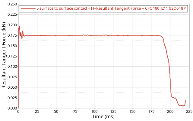
The total normal contact force between the pads and the disc is FN = 0.6 kN and Coulomb friction coefficient= 0.3.
The tangential friction force on the surface of the disc is calculated as FT = 0.3 x FN = 0.18 kN. The orthogonal project from the disc’s center axis to the force application point is r = 77.528 mm. This results in a torque around the axis of the disc of .
From this, an angular deceleration is calculated as:
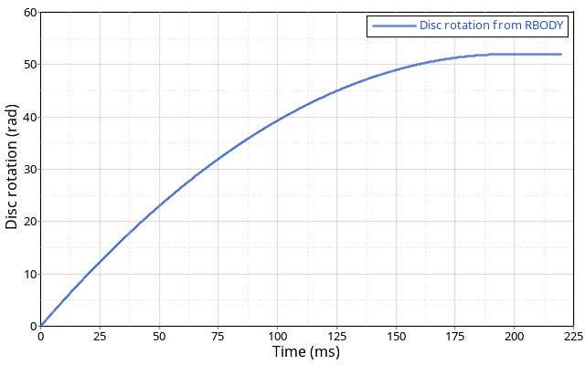
The necessary time to stop the disc can then be computed.
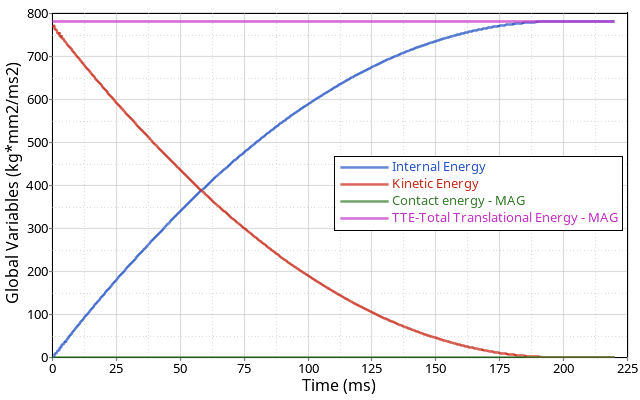
The total energy in the simulation remains constant. The initial kinetic energy is correctly converted into internal energy at the end of the simulation. Contact energy is numerical only and not physical so it should be a small value in the simulation.
Conclusion
The heat generated by contact friction is converted into internal energy and transferred to the disc. The contact force and rotation from the simulation match the analytical results.