RD-E: 2201 Ditching using ALE

Impact of a simple object on water simulated by the ALE approach.


Figure 1.

The ditching of a prism object into a pool of water is studied using the Arbitrary Lagrangian-Eulerian (ALE) approach. The simulation results are compared to the experimental data and analytical results. Furthermore, the study is performed using two different impact velocities. The impacting structure is a triangular prism section. The water is modeled with an ALE mesh while the structure is Lagrangian. The fluid-structure contact interactions are modeled using a /INTER/TYPE18 interface.

Options and Keywords Used

Input Files

Before you begin, copy the file(s) used in this example to your working directory.

Model Description

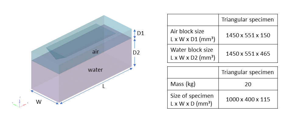
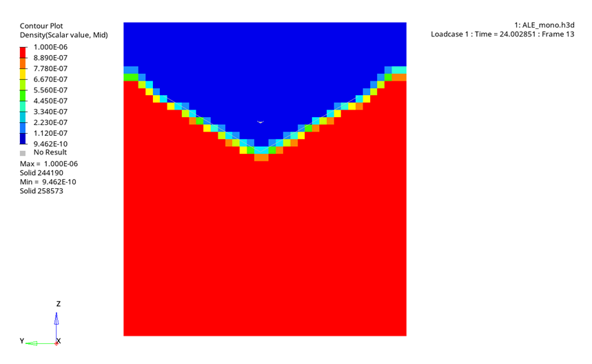
The problem consists of a simple object falling into water simulating the ditching of a helicopter.

Units: mm, ms, KN, GPa, kg

The impact of the triangular prism object on the water is performed and the results are compared qualitatively to analytical results from 2 and also using the experimental data obtained from the Politechnico di Milano. 1

The computation is performed using two impact velocities of 6.7 m/s and 11 m/s.

rad_ex_22_law37
Figure 2. Problem data

The impacting prism is modeled using shell elements with an average mesh size of 15 mm x 15 mm. To shorten the computation, it is made rigid with an accelerometer on the main node of the rigid body.

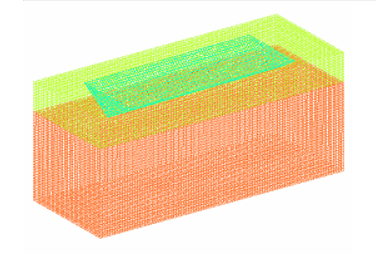
The water is modeled using solid elements consisting of a 15x15x15 mm mesh. The solid element property, /PROP/ TYPE14 (SOLID) is used with Iale = 2 for EULER property formulation.

For modeling air and water /MAT/LAW51 is used utilizing several /MAT/LAW6 as sub-materials as it is the recommended best practice. The input file for the model using /MAT/LAW51 is included as an example.

In one /MAT/LAW51 card, three different phases can be defined. In the current example, two phases, air and water are defined. Air is defined with the following characteristics using sub-material /MAT/LAW6:
  • Initial density (Rho_initial) = 1.22e-09 (kg/m³)
  • EoS_Options_Input (IDEAL_GAS)
  • Heat Capacity Ration (Gamma) = 1.4
  • Initial Pressure (P0) = 0.0001 (Pa)
  • Initial Temperature (T0) = 300 (K)
Water is defined with the following characteristics using sub-material /MAT/LAW6:
  • Initial density (Rho_initial) = 1.0 e-06 (kg/m³)
  • EoS_Options_Input (STIFF_GAS)
  • Heat Capacity Ration (Gamma) = 6.1
  • Initial Pressure (P0) = 0.0001 (Pa)
  • EoS Parameter (P_star) = 0.36885


Figure 3. /MAT/LAW51 material properties

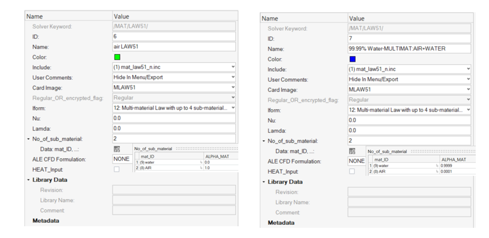
In the multi-material LAW51, the amount of each sub-material is defined. To improve numerical stability, it is recommended to define the water as 99.99% water and 0.01% air.

Boundary Setup

An initial velocity and gravity are applied to the prism in the Z direction.

The boundary conditions are applied to the ALE mesh as:
  • X translation component fixed for lateral faces normal to X
  • Y translation component fixed for lateral faces normal to Y
  • Z translation component fixed for lower and upper faces
Using LAW51 with Iform=6 it is possible to set a non-reflecting boundary without defining any parameters. The material parameters are calculated based on its neighbor element. In this case, one layer of elements needs to be defined as a non-reflecting boundary. The mesh of two corner boundary elements is recommended to be defined (Figure 4).


Figure 4. Boundary mesh treatment

Fluid Structure Interaction (FSI)

An /INTER/TYPE18 interface is defined to manage the contact between the Lagrangian mesh (Prism) and the ALE fluid. The impacting prism is the Lagrangian surface and the ALE fluid is the ALE brick elements group.

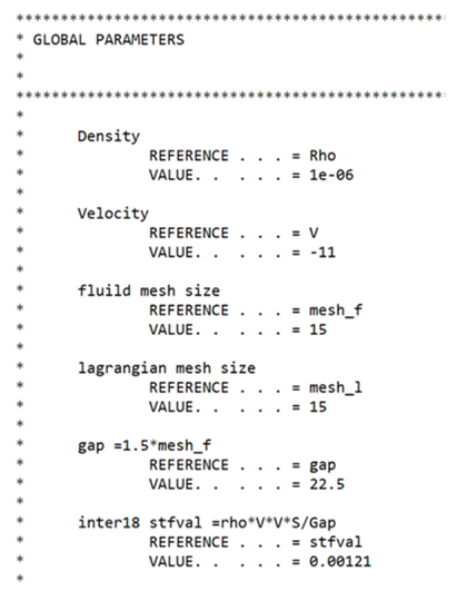
The interface TYPE18 forces are computed using the penalty method. The interface stiffness is proportional to impact velocity. The results obtained by the ALE approach are dependent on the interface stiffness factor S t f v a l MathType@MTEF@5@5@+= feaagKart1ev2aaatCvAUfeBSjuyZL2yd9gzLbvyNv2CaerbuLwBLn hiov2DGi1BTfMBaeXatLxBI9gBaerbd9wDYLwzYbItLDharqqtubsr 4rNCHbGeaGqiVu0Je9sqqrpepC0xbbL8F4rqqrFfpeea0xe9Lq=Jc9 vqaqpepm0xbba9pwe9Q8fs0=yqaqpepae9pg0FirpepeKkFr0xfr=x fr=xb9adbaqaaeGaciGaaiaabeqaamaabaabaaGcbaGaam4uaiaads hacaWG2bGaamyyaiaadYgaaaa@3A99@ , which is a function of the size of the element and fluid properties.(1) S t f v a l = ρ v 2 S e l G a p MathType@MTEF@5@5@+= feaagKart1ev2aaatCvAUfeBSjuyZL2yd9gzLbvyNv2CaerbuLwBLn hiov2DGi1BTfMBaeXatLxBI9gBaerbd9wDYLwzYbItLDharqqtubsr 4rNCHbGeaGqiVu0Je9sqqrpepC0xbbL8F4rqqrFfpeea0xe9Lq=Jc9 vqaqpepm0xbba9pwe9Q8fs0=yqaqpepae9pg0FirpepeKkFr0xfr=x fr=xb9adbaqaaeGaciGaaiaabeqaamaabaabaaGcbaGaam4uaiaads hacaWG2bGaamyyaiaadYgacqGH9aqpdaWcaaqaaiabeg8aYjabgwSi xlaadAhadaahaaWcbeqaaiaaikdaaaGccqGHflY1caWGtbWaaSbaaS qaaiaadwgacaWGSbaabeaaaOqaaiaadEeacaWGHbGaamiCaaaaaaa@4981@
Where,
ρ
The (highest) fluid density
ν
Estimated relative velocity of the phenomenon
S e l
Average surface area of the Lagrangian elements
Gap MathType@MTEF@5@5@+= feaagKart1ev2aaatCvAUfeBSjuyZL2yd9gzLbvyNv2CaerbuLwBLn hiov2DGi1BTfMBaeXatLxBI9gBaerbd9wDYLwzYbItLDharqqtubsr 4rNCHbGeaGqiVu0Je9sqqrpepC0xbbL8F4rqqrFfpeea0xe9Lq=Jc9 vqaqpepm0xbba9pwe9Q8fs0=yqaqpepae9pg0FirpepeKkFr0xfr=x fr=xb9adbaqaaeGaciGaaiaabeqaamaabaabaaGcbaGaam4raiaadg gacaWGWbaaaa@389D@
Contact gap

The recommended Gap value is 1.5 times the average element length of the ALE mesh.

Using the density of water 1e-6 kg m m 3 MathType@MTEF@5@5@+= feaagKart1ev2aqatCvAUfeBSjuyZL2yd9gzLbvyNv2CaerbuLwBLn hiov2DGi1BTfMBaeXatLxBI9gBaerbd9wDYLwzYbItLDharqqtubsr 4rNCHbGeaGqiVu0Je9sqqrpepC0xbbL8F4rqGqFfpeea0xe9vq=Jb9 vqpeea0xd9q8qiYRWxGi6xij=hbba9q8aq0=yq=He9q8qiLsFr0=vr 0=vr0db8meaabaqaciGacaGaaeqabaWaaeaaeaaakeaadaWcaaqaai aadUgacaWGNbaabaGaamyBaiaad2gadaahaaWcbeqaaiaaiodaaaaa aaaa@3C22@ , velocity of 11 m/s, and average Lagrangian shell element area is:(2) S el =15×15=225 MathType@MTEF@5@5@+= feaagKart1ev2aqatCvAUfeBSjuyZL2yd9gzLbvyNv2CaerbuLwBLn hiov2DGi1BTfMBaeXatLxBI9gBaerbd9wDYLwzYbItLDharqqtubsr 4rNCHbGeaGqiVu0Je9sqqrpepC0xbbL8F4rqGqFfpeea0xe9vq=Jb9 vqpeea0xd9q8qiYRWxGi6xij=hbba9q8aq0=yq=He9q8qiLsFr0=vr 0=vr0db8meaabaqaciGacaGaaeqabaWaaeaaeaaakeaacaWGtbWaaS baaSqaaiaadwgacaWGSbaabeaakiabg2da9iaaigdacaaI1aGaey41 aqRaaGymaiaaiwdacaqG9aGaaeOmaiaabkdacaqG1aaaaa@4344@
Then (3) Stfval= 1e6 11 2 225 1.515 =1.21e3 MathType@MTEF@5@5@+= feaagKart1ev2aaatCvAUfeBSjuyZL2yd9gzLbvyNv2CaerbuLwBLn hiov2DGi1BTfMBaeXatLxBI9gBaerbd9wDYLwzYbItLDharqqtubsr 4rNCHbGeaGqiVu0Je9sqqrpepC0xbbL8F4rqqrFfpeea0xe9Lq=Jc9 vqaqpepm0xbba9pwe9Q8fs0=yqaqpepae9pg0FirpepeKkFr0xfr=x fr=xb9adbaqaaeGaciGaaiaabeqaamaabaabaaGcbaGaam4uaiaads hacaWG2bGaamyyaiaadYgacqGH9aqpdaWcaaqaaiaaigdacaWGLbGa eyOeI0IaaGOnaiabgwSixlaaigdacaaIXaWaaWbaaSqabeaacaaIYa aaaOGaeyyXICTaaGOmaiaaikdacaaI1aaabaGaaeymaiaab6cacaqG 1aGaeyyXICTaaeymaiaabwdaaaGaeyypa0Jaaeymaiaab6cacaqGYa GaaeymaiaadwgacqGHsislcaaIZaaaaa@5470@
In this example, parameters are used to automatically recalculate the S t f v a l MathType@MTEF@5@5@+= feaagKart1ev2aaatCvAUfeBSjuyZL2yd9gzLbvyNv2CaerbuLwBLn hiov2DGi1BTfMBaeXatLxBI9gBaerbd9wDYLwzYbItLDharqqtubsr 4rNCHbGeaGqiVu0Je9sqqrpepC0xbbL8F4rqqrFfpeea0xe9Lq=Jc9 vqaqpepm0xbba9pwe9Q8fs0=yqaqpepae9pg0FirpepeKkFr0xfr=x fr=xb9adbaqaaeGaciGaaiaabeqaamaabaabaaGcbaGaam4uaiaads hacaWG2bGaamyyaiaadYgaaaa@3A99@ depending on impact velocity and mesh size. This makes it easy to study different velocities and the parameters can be used in other models. The input and calculated parameters from a simulation are printed in the Starter output file.


Figure 5.

Results


Figure 6. Density results for LAW51
Acceleration results from the ALE simulation using LAW37 and LAW51 were filtered with a CFC 60, -3 dB filter and are compared to Von Karman theoretical solution and experimental results filtered with a CFC 60, -3 dB filter.


Figure 7. Acceleration results for 11 m/s for simulation, theoretical solution, and experimental test

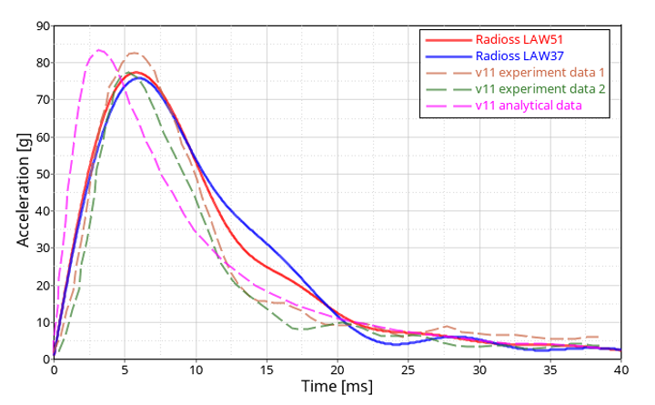
The ALE method results in a maximum acceleration of 77.3 g for LAW51 and 75.8 g for LAW37. However, the Von Karman theoretical solution delivers 83.5 g. The maximum value from the test is between 82.8 g and 77.5 g.

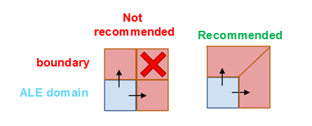
In general, the ALE results match the analytical and experiment curve, especially at the duration for acceleration beyond 40 g. Using material LAW51 is recommended because it results in a more discrete boundary at the fluid-structure interface.