Connector Entity Browser
The Connector Entity Browser contains a list of all the connections contained in the model, and has its own set of tools similar to the ones found in the Link Entity Browser.
All the connectors in the model are displayed in folders organized by tabs based on the respective type. The All Tab contains a list view of the connectors in the model. Each type of connector has its own tab with a flat list of connectors.
The connector information in the specific tabs can be used to find link entities connected by specific connectors, and also to modify certain connector attributes. The columns display a sub-set of connector information that is important for recognizing connection information easily.
- General: all of the links are within the same subsystem.
- Subsystem: one or all of the links are in multiple subsystems.
- Attachment: a new single lined connector entity.
- 1st connector entity
- Selected connectors.
- linked entities
- Links which are referenced by one of the selected connectors.
This kind of categorical separation is only used for the actions show, hide, isolate and isolate only, and only when one of the view option toggle buttons is active, regardless of whether the actions are taken from the context menu. No other functionality uses this categorization at all.
You can also change the base features of the Connector Entity Browser in the Connector Entity Browser configuration window.
| Option | Description |
|---|---|
| Entities | ID of the connector and an image that represents the respective connector’s style (spot, seam, bolt, and so on). |
| Status | Realization state of the connector entity:
unrealized, realized,
failed, or
modified. Note: For those writing scripts
instead of using the GUI, a more detailed report can be
created by using the following lines in your script:
set error_report [ hm_ce_errorreport CE_ID 1
                                            ]
. |
| Tolerance | Realization tolerance of the connector. You can change this by right-clicking the field and typing in a new value, then pressing Enter. |
| Link | ID or name of the entity added as a link to a connector. |
| Layer | Total number of link entities to be joined by the connector. This is also marked as thickness layers (2T/3T/4T, and so on). |
| Subsystem | Displays connectors associated with a subsystem. |
| Connector Group | Name of the Connector Group to which the connector belongs. |
| Comment | Input comments for a connector. |
| Error Message | Error messages for a connector. |
Functionality is accessed from the global display tool set, an action modes tool set and a right-click context menu.
View Option Toggle Buttons
These options determine the entities that display when you select and then show, hide, or isolate a supported entity.
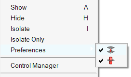
Each button is modal, that is, you click it once to activate it, and click it again to deactivate it. Active buttons remain active until you specifically deactivate them, so you do not need to worry about them "resetting" after you perform an action such as isolate.
| Option | Name | Effect |
|---|---|---|
| Linked entity | Finds the link entities/supported entities to which the
selected connector connects. If this linked entity view option button is active, all entities linked to the 1st connector entities will be taken into account for the action. It does not matter if the 1st connector entity view option button is active or inactive, its entities will still be located. This determination has nothing to do with any display states. This means that in case of isolation, only the
entities which are referenced by the selected connectors
(1st connector entity) are isolated. 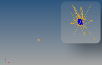 |
|
| Realization | Finds and displays the realization for the selected connectors. |
Cumulative Effect of Multiple View Options
These options work accumulatively, for example, when both the Linked entity and 2nd connector entity buttons are active, then selecting and isolating a connector displays the component that it links to, and all the other connectors that link to that component. If you had Realization, Linked entity, and 2nd connector entity active when you isolated the same connector, then the model would display the component to which the connector links, all other connectors linking to that component, and the realizations of each displayed connector.
Context Menu
The Connector Entity Browser context menu includes all of the functionality available in the Connector Entity Browser, including connector creation and deletion, renumbering, updating, finding connectors, and much more.
The tools available in the context menu vary depending on what you right-click on; for example, right-clicking on a connector (in the Entities column) accesses the full menu, but right-clicking a link (in the Link 1 or Link 2 columns) only presents the Remove Link option.
| Option | Description |
|---|---|
| Create | Choose the type of connector to create, then define connector settings in the related connector tool that opens. |
| Delete | Delete connectors or connectors and their related FE elements. |
| Convert | Convert connectors to a different type, for example a spot
connector into a bolt connector. For more information, see Convert Style. |
| Combine | Combine single point connectors into line connectors, for
example several spot connectors into a spotline connector. For more information, see Combine. |
| Split | Split line connectors into single point connectors, for
example a spotline connector into several spots. For more information, see Split. |
| Position | Position connectors to the center between the farthest links
or back to their source position. For more information, see Position. |
| Disassociate FE | |
| Organize | Open the Organize Connectors dialog from which you can organize connectors into different Connector Groups. |
| Update layer | Update the Layer field, which becomes editable in Connector
Entity browser, to input the layer value that you wish to assign
to the selected connectors (this function works for multiple
selections). Enter the desired number of layers into the text box and press Enter. The layer value defines the number of thicknesses (2T/3T/and so on) a connector connects at its location. The layer value defined in a connector can be greater than or equal to number of links connected by the connector. The connectors will be unrealized after this update, but the change is recorded permanently in the database and in the browser. Alternatively, you can also update the layer directly by right-clicking on the field itself rather than using the context menu. |
| Update tolerance | Update the Tolerance field, which becomes editable in
Connector Entity browser, to input the tolerance value that you
wish to assign to the selected connectors (this function works
for multiple selections). You can also do this directly by right-clicking on the field itself rather than using the context menu. |
| Update diafactor | Update the diafactor field, which becomes editable in
Connector Entity browser, to input the diafactor (diameter
factor) value that you wish to assign to the selected
connectors. This function works for multiple selections. You
can also do this directly by right-clicking on the field
itself rather than using the context menu. Note: The diafactor field is
shown for any connector of any type. This value is
mainly used for specific bolt realizations; all others
get "NA" by default for this field. Although you can
update "NA" to any value, the value is ignored during
realization. |
| Update diameter | Opens a dialog to enter the diameter value that you wish to
assign to the selected connectors. This function works for
multiple selections. You can also do this directly by
right-clicking on the field itself rather than using the
context menu. Note: The diameter
field is shown for any connector of any type. This value
is not necessary for many realization types; they get
per default NA for this field, though you can update NA
to any value. This value is ignored then during
realization. |
| Add Link | Opens a new set of controls in the bottom of the tab to add
links to the selected connectors. For more information, see Add Link. |
| Update Link | Opens a new set of controls in the bottom of the tab to
perform a part replacement. Note: Editing a connector causes it
to become unrealized. 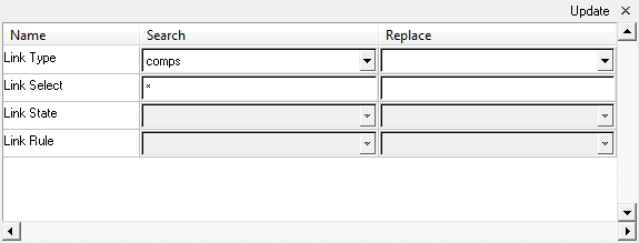 |
| Remove Links | Remove all of the links from the selected connectors. The connectors will be unrealized and the change is recorded permanently in the database and in the browser selected connectors or all connectors in the browser. The connectors will be unrealized and the change is recorded permanently in the database and in the browser. |
| Combine Links | Combines individual links on a connector to Link Group.
Combining links might be useful because, for each Link Group, a
valid projection has to be considered for each connector point.
This prevents choosing the wrong link in certain
situations. Note: Combining links causes connectors to become
unrealized. |
| Convert Links | Convert links to one of the following link types: Part, Comp,
or Prop. For more information, see Convert Links. |
| Change Link Rule | The link rule defines how a connector treats an entity added as a link. Adding a link with the ID or name rule forces the connector to retain the link’s ID or name even if that link entity no longer exists in the database. |
| Change Link Structure | The link state defines if the weld created during connector realization connects to geometry or mesh on the link. This is applicable to only components and surfaces entities that can contain geometry and/or mesh information. |
| Copy Attributes | Copy all attributes of selected connectors. |
| Paste Attributes | Paste all attributes of selected connectors. |
| Realize | Calls the *CE_Realize command to realize
connectors by accepting only a connector mark. The underlying
assumption in the command is that each connector passed in the
mark has the required information to be successfully
realized. The required information such as tolerance, weld configuration, diameter, and so on is not defined for connectors created using the FE Absorb utility; hence the Rerealize feature in the Connector Browser works only for connectors that were realized through an HyperMesh Connector panel. |
| Unrealize | Unrealizes the selected connectors. |
| Realize Modified | Realizes the selected modified connector. |
| Connector Comparison Tool | Opens the Connector Comparison Tool panel. |
| Connector Quality Tool | Opens the Quality Panel (Connectors) panel. |
| Fine Components with FE Tool | The entities that are linked in the selected connectors are
isolated in the display with the connectors. If the realization
view option |
| Find Connectors from Elems Tool | Imports connectors from elements. |
| Import Connectors MCF Tool | Imports MCF connectors. |
| References | Opens the Reference Browser and displays the relationship of the selected entities to other entities in the model, in a hierarchical tree structure. |
| Review | Invokes review mode, which displays selected entities. If the connectors are realized, it displays realizations. If the connectors are unrealized, it shows connectors. |
| Show | Shows selected entities. |
| Hide | Hides selected entities. |
| Isolate | Displays only the selected entities, turning their display state to on and turning all other entities of the same type off. Isolate works locally within a specific entity type – for example, if component(s) are isolated, then all display states of other displayable entities, such as load collectors, remain untouched. |
| Isolate Only | Works like Isolate, except that it also affects entity types different from the matching, selected entities. Thus, it turns off ALL displayable entities, regardless of type, except for the selected one(s). |
| Expand | This option expands all the folders to display all the connectors. This operation may take some time for folders that contain thousands of connectors. |
| Collapse | This option closes all the expanded folders in the browser. |
| Control Manager | Opens the Control Manager dialog. |
| Connector Appearance | Opens the Connector Appearance dialog. |
| Configure Browser | Opens the Configuration Window which contains options to configure the Connector Browser's list display and button behavior. |
Configuration Window
In the Browser Configuration dialog you can select which columns to display in the browser, and change the way special tools, such as find twin connectors, operate.
Open the Browser Configuration dialog by right-clicking in the Connector Entity Browser and selecting Configure Browser from the context menu.
Local Options
- Max Link Column Viewed
- Regardless of how many links a connector might have, the browser will only display the specified number of columns.
- Show Primary Links Only
- By default, both primary and secondary links are displayed in the browser. To only display primary links, select the Show Primary link only checkbox.
- Show Node Attachment Label
- Show the name of the node attachment in the modeling window.
- Auto-Create Parts for Realization
- Create parts in Part Browser to hold the realization component nested under a part configuration.
- Consider Geometry
- Consider geometry along with elements while using Show/Hide/Isolate
operations.
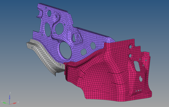
Figure 5. Consider Geometry: Off 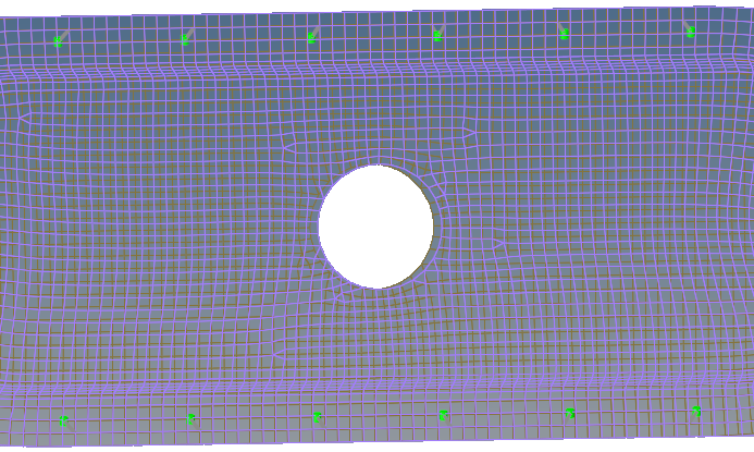
Figure 6. Consider Geometry: On 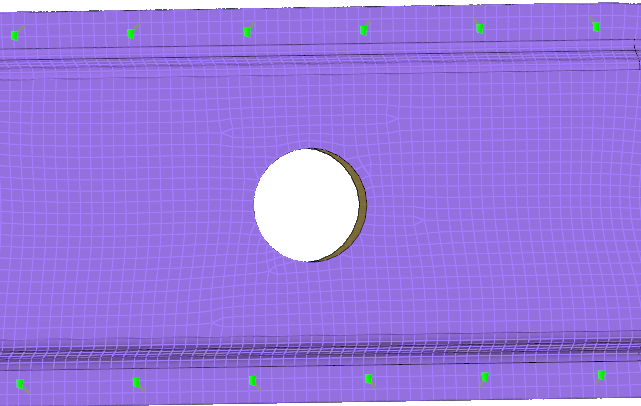
- Consider HAZ Elements
- Consider HAZ elements while using Show/Hide/Isolate operations. When this option is on, and if connectors are isolated, HAZ elements are also isolated along with connectors and their links.
- Available for Connector Configure browser options.
Figure 7. Consider HAZ Elements: Off. HAZ elements of hexa Nugget connectors are not isolated along with connectors and linked components. 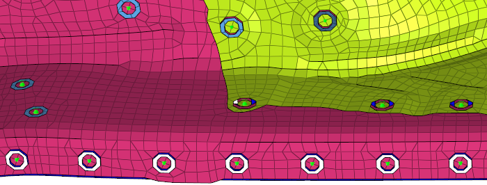
Figure 8. Consider HAZ Elements: On. HAZ elements of hexa Nugget connectors are isolated along with connectors and linked components. 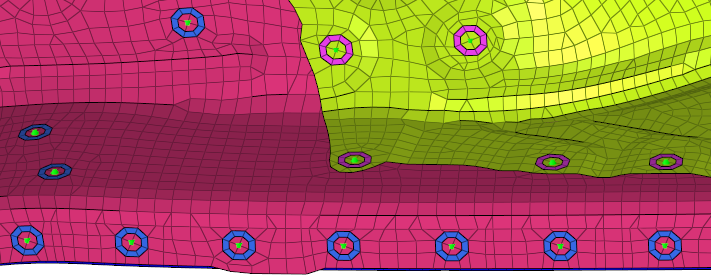
- Find Connectors Between With
- Select how connectors between selected links are found:
- Minimum two selected links
- Only connectors that link to at least two selected entities will be affected. Connectors with only one link to any of the selected entities will be ignored.
- Exact selected links
- Only connectors that link to the selected entities will be affected. This can vary from the Minimum two selected links option, because connectors with three or more links which link two selected entities with at least one unselected entity, would still be found by the Minimum two selected links option but not by this one.
- All selected links
- Any connector shared by the selected entities will be
found.Note: Connectors which link selected entities to any unselected ones will not be found, as they are not located between the selected entities.
- Filter Links To
- Choose which links to filter when performing search/isolation
functions.
- Projection Components
- Isolate the entire link component.
- Projection Elements
- Isolate only the elements on which a projection falls.
- Projection and Attached Elements
- Isolate only the elements on which the projection falls and the elements which the connector FE connects.
-
Filter Links To Projection Components Projection Elements Projection and Attached Elements Spots Figure 9. 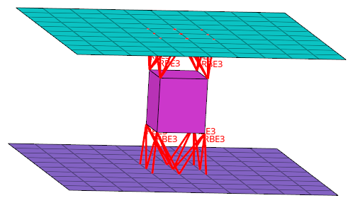
Figure 10. 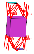
Figure 11. 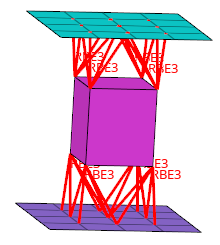
Seams Figure 12. 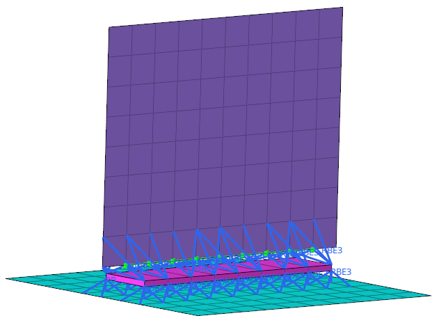
Figure 13. 
Figure 14. 
Bolts Figure 15. 
Figure 16. 
Figure 17. 
Global Options
- Autocolor Visualization Mode
- Automatically switch the element color mode when accessing different tabs in the Connector Link Entity Browser.
- Live-filtering
- Filter items in real time.