Create Tracks
Wrapping Type
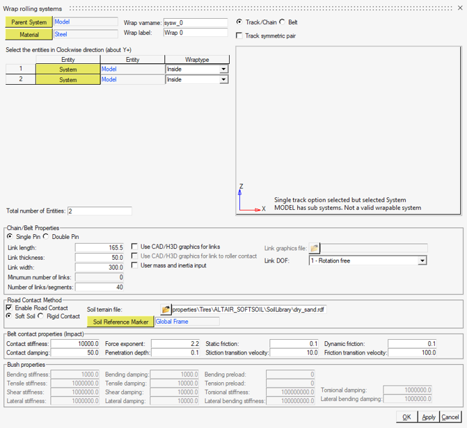
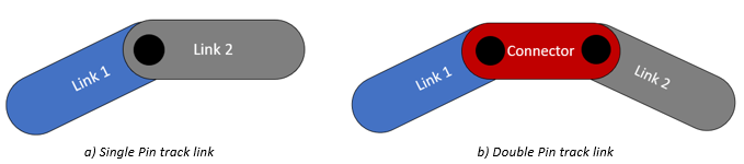
The Track/Chain or Belt option are available to create different types of wrapping. The difference between the wrapping types relies on the contact applied. When the CAD/H3D graphics option is not used, the Track/Chain uses sphere-to-sphere contact between the sprocket and track and sphere-to-box contact for other entities and the track. The belt uses sphere-to-sphere contact between all entities and the belt.
Wrapping Rolling System
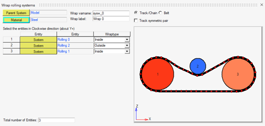
The dialog automatically provides a preview of the wrap system as soon as enough input data has been provided. If a wrap fails, error messages are displayed in the bottom of preview area. Catenary sag is included if more links than the minimum required amount are present. Conversely, if the number of links are less than the minimum amount, the track will be open. In that case, a flexible stiffness entity is created to connect the first and last link to close the gap during simulation. This causes tension within the track as soon as the simulation starts and might be preferred by design.

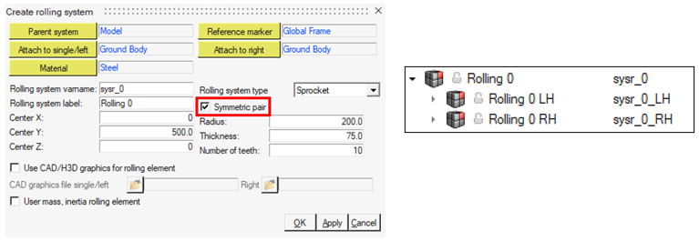
In the Wrapping rolling systems dialog with the Symmetric pair option enabled, the rolling parent system must be selected. In the case where the rolling systems were created as pairs, but the wrap must be done individually, clear the Track symmetric pair option and select the left (LH) or right (RH) systems to create the individual wrap. It is important to be consistent in your choices, either selecting all right or all left rolling components when creating a single track.
Track Properties
The option Use CAD/H3D graphics for link to roller contacts enables
the 3D rigid contact between the CAD or H3D file of the rolling systems. If the rolling
components do not have CAD/H3D files, this option cannot be used and the message
“Contact graphics not found” will be shown in the track preview
window.
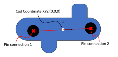
User-defined mass and inertia can be provided using the option User mass and inertia, in this case the track links properties can be edited in the wrap system dataset.
| Link DOF (degree of freedom) | Connection | Lateral Constraint | Geometry Option Supported |
|---|---|---|---|
| 1 - Rotation free | Revolute joint for all links and Inline joint between the first and last link. | Planar | Primitives and CAD |
| 1 - Rotation and bending stiffness | Revolute joint for all links and Inline joint between the first and last link. Rotational stiffness and bending preload are supported between all links. | Planar | Primitives and CAD |
| 2 - Tensile and bending stiffness | Planar joint and Inplane primitive for all links. Rotational stiffness and bending preload between all links are supported, as well as tensile stiffness and tensile preload. | Planar | Primitives and CAD |
| 6 - All direction stiffness | Tensile stiffness and Tensile preload between all links. This option supports rotational, lateral, shear, torsional, and lateral-bending stiffness, as well as bending preload between all links. | None | Only CAD |
Road Contact Method
- Soft Soil
- Rigid Contact
- Soft Soil
- The Altair Soft Soil model provides a way to simulate the dynamic behavior of a
track system on a surface that is compressible such as clay, dry sand, regolith, and
ice-covered snow. Refer to Soft Soil Track Model for more
information.
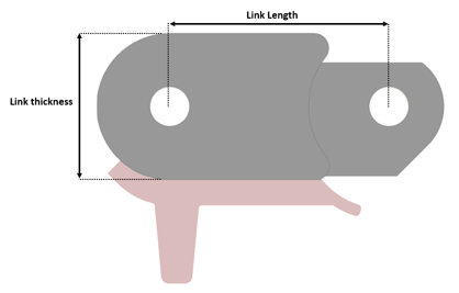
In MotionView, a force entity is created at the center of each track link containing the track soil contact equations. The parameters defined in the track properties are used to compute the soil interaction. Depending on the shape of the track link it is required to update the track link geometry as shown in Update Link Geometries.
When soft soil interaction option is selected the Soil Terrain file and the Soil Reference Marker properties are displayed.Figure 9. Road Contact Method dialog 
The Soil Terrain file requires the soft soil road model containing the soft soil and track soil parameters. A soft soil road library containing ready-to-use road data files for a variety of soils are located in the installation <Installation>\hwdesktop\hw\mdl\autoentities\properties\Tires\ALTAIR_SOFTSOIL. For more information on how to build a soft soil road model see Road Modeling.
The Soil Reference Marker requires a marker entity where the soil origin will be positioned at.Note: Load the soft soil road file .rdf in the Road Tools to create a graphic representation of the soft soil road in MotionView. For more information see Road Tools. - Rigid Contact
- The rigid contact soil interaction uses MotionSolve 3D
rigid contact method between the track geometry and a road geometry specified in
Terrain Graphics Files to capture the track-road
dynamics.
Figure 10. Rigid contact soil interaction dialog 
The Terrain Graphics file requires a CAD or H3D graphics following MotionView’s and MotionSolve’s recommendation for modeling contact. See Contacts and Best Practices for Running 3D Contact Models in MotionSolve.
The contact friction parameters, Static and Dynamic friction, Stiction transient velocity, and Friction transition velocity can be modified in the Rigid Contact soil interaction option. The normal force contact parameters are specified in the Contact Properties section.
After creating the track system, all parameters can be modified in the wrap system datasets.
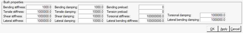
Contact Properties

After creating the track system, all parameters can be modified in the wrap system datasets.
Outputs
- Track tension – output the tension force in the track by measuring the longitudinal force on track link connection joint or bushing in its local coordinate system.
- Contact Forces – output the contact force of each link with each rolling component.