Soft Soil Track Model
The Altair Soft Soil model provides a way to simulate the dynamic behavior of a track system on a surface that is compressible such as clay, dry sand, regolith, and ice-covered snow.
Theoretical Approach
In the current track model, the deformations of the soil which eventually lead to the corresponding (normal and shear) stresses are considered as two independent effects. Specifically, the strength of the soil is considered in the normal direction (pressure-sinkage relationship) as well as in the tangential direction (shear stress-shear displacement relationship).
Pressure-Sinkage Relationship
If a terrain is assumed to be homogeneous, its pressure-sinkage relationship (the result of the plate-sinkage test) may take one of the forms which are shown in Figure 1, and it may be characterized by the following empirical equation proposed by Bekker. [1]
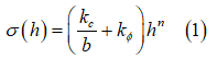
Where  is pressure,
  is the width of the rectangular contact patch area,
  is sinkage, and
  , and
, and  , are pressure-sinkage related parameters.
Soil Failure
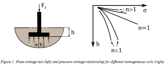
There is a variety of criteria proposed for the failure of soils. One of the most widely
used is the Mohr-Coulomb criterion which states that the maximum shear strength  of the soil is:
Where  is the apparent cohesion,
  is the normal stress, and
  is the angle of internal shearing resistance of the material. The
aforementioned parameters can be derived with a shear test for different pressures, as shown
in Figure 2:
is the angle of internal shearing resistance of the material. The
aforementioned parameters can be derived with a shear test for different pressures, as shown
in Figure 2:
Track-Road Interaction
Contact Points
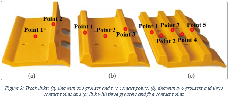
Within the track model, the number of contact points varies in the range 1-5 depending on the shape of the track link. More specifically, in the case of one (1) contact point, only a flat area is used for the description of the track link shape, whereas grousers are added for the cases of more than one (2-5) contact points. In Figure 3, three different examples of the track link shape are presented for the cases of two, three and five contact points, respectively.
Normal Stress
Using the pressure-sinkage relationship proposed by Bekker (Equation (1)), the track link normal stress is provided by [2, 3]
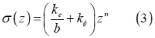
where  is the sinkage of the track link, while the definition of the
parameter b is provided by the user. In particular, the width or the minimum dimension of
the track link can be used for the definition of this parameter.
is the sinkage of the track link, while the definition of the
parameter b is provided by the user. In particular, the width or the minimum dimension of
the track link can be used for the definition of this parameter.
Furthermore, Equation (3) can be modified in order to account for the contribution of soil damping [2-4]. In that case, the normal stress is given by
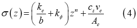
where  is the soil damping,
  is soil’s compression rate/velocity, and
  is the contact patch area.
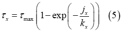
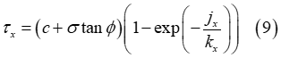
Shear Stress
The shear stresses  and
and  are calculated using identical expressions [2-3], [5].
In the above equations,  and
and  denote the shear displacements in x and y direction,
respectively. In addition,
denote the shear displacements in x and y direction,
respectively. In addition,  and
and  represent the shear deformation modules, which are provided by
the following equations:
represent the shear deformation modules, which are provided by
the following equations:
where  and
and  are constant terms.
and can be found in the following publications:- ‘Soil-tire interaction analysis for agricultural tractors: Modeling of traction
performance and soil damage’ by A. Battiato, 2014 [6]
 [m] for clay
 [m] for clay loam
 [m] for silty loam
 [m] for loamy sand
- ‘Terramechanics-based analysis for slope climbing capability of a
lunar/planetary rover’ by K. Yoshida and G. Ishigami, 2004 [7]
 [m] for dry sand
 [m] for regolith simulant
- ‘Analysis of off-road tire-soil interaction through analytical and finite
element methods’ by H. Li, 2013 [4]
 [m]
[m] [m]
[m]
Moreover, according to Wong [8], based on experimental data collected, the value of ranges from 0.01 [m] for firm sandy terrain to 0.025 [m] for
loose sand and is approximately 0.006 [m] for clay at maximum compaction. For undisturbed
fresh snow, the value of varies in the range from 0.025 [m] to 0.05 [m].
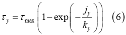
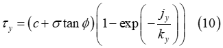
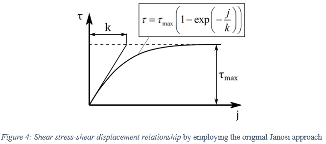
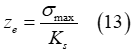
Using the original Janosi approach, the maximum shear strength of the soil, provided by Equation (2), is substituted in Equations (5)-(6) for the calculation of the shear stresses, resulting in the following expressions
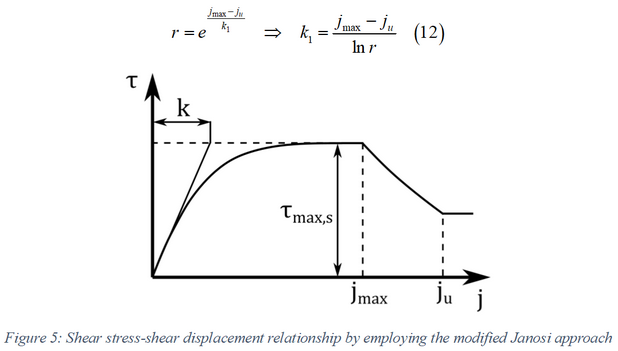
However, due to the soil failure, the shear stress decreases above a certain value of shear-displacement [3]. Herein, a simple approach is proposed in order to account for this effect, where the maximum shear strength of the soil constitutes a function of the shear–displacement [3]. Based on this, a modified Janosi approach is derived in the form
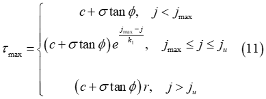
where  corresponds to the value of the shear displacement where the soil
failure starts and
corresponds to the value of the shear displacement where the soil
failure starts and  stands for the ultimate shear displacement, that is above this
value the shear stress is unaffected by the shear displacement
stands for the ultimate shear displacement, that is above this
value the shear stress is unaffected by the shear displacement  . Moreover, the parameter r denotes the maximum shear ratio
  .
.
In addition, the following expression must hold such that the maximum shear strength, given by Equation (11), corresponds to a continuous function
Grouser Effect
The proper modeling of the grouser forces is crucial for the track model since their contribution to the total forces of the track link can be very significant. It turns out that the soil–grouser interaction is very similar to the soil–blade interaction. Therefore, the model proposed by McKyes [9] is suitable for the proper modeling of this interaction. Within this work, the model proposed by McKyes [9] is used for the calculation of the grouser forces with some modifications [3].
Multipass Effect
- Normal Stress
-
For the multipass effect, the response of the soil to repetitive normal load needs to be established. Specifically, the mathematical description of the normal stress must be modified in cases of existing pre-compaction of the soil. As shown in Figure 6, the normal stress will be comprised initially from an elastic part
 , which is equal to the elastic (unloading) sinkage that
has already been created due to the interaction of the soil with a track link. Then,
the pressure-sinkage relationship continues according to Equation (3). Finally, an
unloading elastic part
, which is equal to the elastic (unloading) sinkage that
has already been created due to the interaction of the soil with a track link. Then,
the pressure-sinkage relationship continues according to Equation (3). Finally, an
unloading elastic part  is encountered.
One part of the induced soil deformation is elastic (elastic sinkage), and the remaining part (plastic sinkage) is irreversible. The elastic part is provided by the equation
where
 is the soil elastic stiffness.
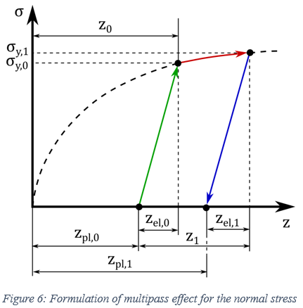
- Shear Stress
-
A similar approach to the normal stress is also employed for the description of the multipass effect for the shear stress. Specifically, the soil shear stress, is initially, formulated as a function of the shear displacement by using the equation
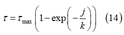
until certain (maximum) values of the shear stress and shear displacement are derived. Subsequently, a linear unloading/loading curve is created based on the maximum values of the shear-related parameters, as depicted in Figure 7. The induced plastic shear displacement of the soil is provided by the expression
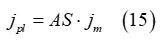
where
 is the (current) maximum value of the shear displacement
and AS constitutes a user-defined parameter that describes the shear plasticity of
the soil
is the (current) maximum value of the shear displacement
and AS constitutes a user-defined parameter that describes the shear plasticity of
the soil 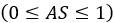 . In particular, for
  , the whole induced shear displacement of the soil is
elastic, whereas for
, the whole induced shear displacement of the soil is
elastic, whereas for  the shear displacement is entirely plastic.
Apparently, this linear curve describes the shear stress-shear displacement relationship for values of the shear displacement in the range
 . On the contrary, for
  , the initial curve, given by Equation (14), is again
used. Lastly, it should be noted that a similar approach is also employed for the
description of the multipass effect for the grouser force by using the parameter AM
instead of the parameter AS [3].
, the initial curve, given by Equation (14), is again
used. Lastly, it should be noted that a similar approach is also employed for the
description of the multipass effect for the grouser force by using the parameter AM
instead of the parameter AS [3].
MotionSolve Output Requests
- Soil force in the global direction with respect to the reference marker for each link.
- Soil normal force in the link local coordinate for each link.
- Sinkage, longitudinal slip, and lateral slip for each link.
- Total soil force for each wrap.
- Total soil force for all links in all wraps.
The force output for contacts can be created for all the contacts using the Entity set option in the output request. The output for forces like tension or bending force can be measured on the respective joint and or force. The mid marker in the link can be used as a reference marker for the force.
References
[1] M.G.Bekker, Introduction to terrain-vehicle systems. part i: The terrain. part ii: The vehicle. Michigan Univ Ann Arbor, 1969.
[2] D. Rubinstein and R. Hitron, “A detailed multi-body model for dynamic simulation of off-road tracked vehicles,” Journal of Terramechanics, 41(2-3), 163-173, 2004.
[3] D. Rubinstein and J. L. Coppock, “A detailed single-link track model for multi-body dynamic simulation of crawlers,” Journal of Terramechanics, 44(5), 355-364, 2007.
[4] Hao-Li, “Analysis of Off-Road Tire-Soil Interaction through Analytical and Finite Element Methods,” Technischen Universität Kaiserslautern, 2013.
[5] Z.Janosi, “The analytical determination of drawbar pull as a function of slip for tracked vehicles in deformable soils,” in Proc. of 1st Int. Conf. of ISTVS, 1961.
[6] A.Battiato, “Soil-tyre interaction analysis for agricultural tractors: modelling of traction performance and soil damage,” 2014.
[7] K. Yoshida, N. Mizuno, G. Ishigami, and A. Miwa, “Terramechanics-based analysis for slope climbing capability of a lunar/planetary rover,” in 24th Int. Symp. on Space Technology and Science, 2004.
[8] J.Y.Wong, Theory of ground vehicles. John Wiley & Sons, 2008.
[9] E.McKyes, Agricultural engineering soil mechanics. Elsevier, 2012.
[10] J.Y.Wong, Terramechanics and off-road vehicle engineering: terrain behaviour, off-road vehicle performance and design. Butterworth-heinemann, 2009.
[11] J.Y.Wong and A.R.Reece, “Prediction of rigid wheel performance based on the analysis of soil-wheel stresses Part I. Performance of driven rigid wheels,” J. Terramechanics, vol. 4, no. 1, pp. 81–98, 1967.
[12] I. Genya, M. Akiko, N. Keiji, and Y. Kazuya, “Terramechanics-Based Model for Steering Maneuver of Planetary Exploration Rovers on Loose Soil,” J. F. Robot., vol. 7, no. PART 1, pp. 81–86, 2015, doi: 10.1002/rob.