Road Modeling
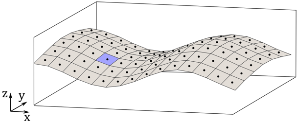
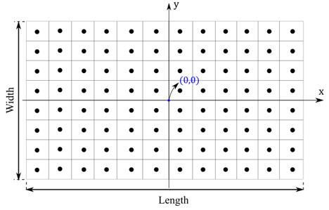
The soft soil road surface is represented as a rectangular structured grid of deformable springs in the vertical (z-axis) direction, as shown in the figure below. Using this approach, each spring represents a small road patch for which the necessary information is stored.
Soil Library
A soil library containing ready-to-use road data files for a variety of soils are located in the installation <Installation>\hwdesktop\hw\mdl\autoentities\properties\Tires\ALTAIR_SOFTSOIL.
Road Data File
All the necessary (and optional) parameters for the soft-soil model are provided in the road data (.rdf) file. It can be used with tires, tracks, or both models. The soil properties are structured into Common Soil Properties, Tire Soil Properties, Track Soil Properties, and Advanced Track Soil Properties.
| Parameter | Description |
|---|---|
| PHI | Angle of internal shearing resistance [Units: angle] |
| C | Soil apparent cohesion [Units: force/length**2] |
| KC | Pressure-sinkage parameter [Units: force/length**(n+1)] |
| KPHI | Pressure-sinkage parameter [Units: force/length**(n+2)] |
| SINKAGE_EXPONENT | Sinkage exponent n [Units: -] |
| SOIL_STIFFNESS | Soil elastic stiffness [Units: force/length**3] |
| SOIL_DAMPING | Soil damping [Units: force*time/length] |
| SOIL_DENSITY | Soil density [Units: mass/length**3] |
| KX1 | Shear deformation module [Units: length] |
| KY1 | Shear deformation module [Units: length] |
| Parameter | Description |
|---|---|
| KX0 | Shear deformation module [Units: length] |
| KY0 | Shear deformation module [Units: length] |
| C1 | Parameter for wheel angle of maximum normal stress [-] |
| C2 | Parameter for wheel angle of maximum normal stress [-] |
| Parameter | Description |
|---|---|
| R_CASE | The input report of the soft-soil model (0≤R_CASE≤2)
|
| WID_OR_MIN | Definition of Bekker parameter b (1≤WID_OR_MIN≤2)
|
| Parameter | Description |
|---|---|
| DELTA | The internal angle of soil-grouser friction. If DELTA<0, then DELTA=PHI*|DELTA| |
| CA | The cohesion between the soil and the grouser. If CA<0, then CA=C*|CA| |
| R_JAN | r of modified Janosi |
| JMAX | jmax of modified Janosi If JMAX<0, then JMAX=|JMAX|*(Link length) |
| JULT | ju of modified Janosi If JULT<0, then JULT=|JULT|*(Link length) |
| AS | The plasticity factor of the shearing (0≤AS≤1) |
| AM | The plasticity factor of the grouser force (0≤AM≤1) |
| PHI_LONG | The internal angle of soil friction. This value is used for the interaction between a link and the soil in the longitudinal direction. PHI_LONG=PHI*PHI_LONG |
| DELTA_LONG | The internal angle of soil-link friction. This value is used for the interaction between a link and the soil in the longitudinal direction. DELTA_LONG=DELTA*DELTA_LONG |
| C_LONG | The cohesion of the soil particles. This value is used for the interaction between a link and the soil in the longitudinal direction. C_LONG=C*C_LONG |
| CA_LONG | The cohesion between the soil and the grouser. This value is used for the interaction between a link and the soil in the longitudinal direction. CA_LONG=CA*CA_LONG |
| PHI_LAT | The internal angle of soil friction. This value is used for the interaction between a link and the soil in the lateral direction. PHI_LAT=PHI*PHI_LAT |
| DELTA_LAT | The internal angle of soil-link friction. This value is used for the interaction between a link and the soil in the lateral direction. DELTA_LAT=DELTA*DELTA_LAT |
| C_LAT | The cohesion of the soil particles. This value is used for the interaction between a link and the soil in lateral direction. C_LAT=C*C_LAT |
| CA_LAT | The cohesion between the soil and the grouser. This value is used for the interaction between a link and the soil in the lateral direction. CA_LAT=CA*CA_LAT |
| CJ1 | Cohesion, c of the Janosi approach, for the longitudinal direction. CJ1=C*CJ1 |
| CJ2 | Cohesion, c of the Janosi approach, for the lateral direction. CJ2=C*CJ2 |
| PHIJ1 | Angle of internal friction, φ of Janosi, for the longitudinal direction. PHIJ1=PHI*PHIJ1 |
| PHIJ2 | Angle of internal friction, φ of Janosi, for the lateral direction. PHIJ2=PHI*PHIJ2 |
| RJ1 | r of the modified Janosi, for the longitudinal direction. RJ1=R_JAN*RJ1 |
| RJ2 | r of the modified Janosi, for the lateral direction.
Recommended value: RJ2=-1. |
| JMAX1 | jmax of modified Janosi, for the longitudinal direction. JMAX1= JMAX*JMAX1 |
| JMAX2 | jmax of modified Janosi, for the lateral direction. JMAX2= JMAX*JMAX2 |
| JULT1 | ju of modified Janosi, for the longitudinal direction. JULT1=JULT*JULT1 |
| JULT2 | ju of modified Janosi, for the lateral direction. JULT2=JULT*JULT2 |
| AS1 | The plasticity factor of the shearing (0≤AS1≤1). The index 1 indicates the longitudinal direction. AS1=AS*AS1 |
| AS2 | The plasticity factor of the shearing (0≤AS2≤1). The index 2 indicates the lateral direction. AS2=AS*AS2 |
| AM1 | The plasticity factor of the grouser force (0≤AM1≤1). The index 1 indicates the longitudinal direction. AM1=AM*AM1 |
| AM2 | The plasticity factor of the grouser force (0≤AM2≤1). The index 2 indicates the lateral direction. AM2=AM*AM2 |
Property File Example
$----------------------------------------------------------------MDI_HEADER
[MDI_HEADER]
FILE_TYPE  =  'rdf'
FILE_VERSION  =  5.00
FILE_FORMAT  =  'ASCII'
$---------------------------------------------------------------------UNITS
[UNITS]
 LENGTH              	= 'm'
 FORCE               	= 'newton'
 ANGLE               	= 'radians'
 MASS                	= 'kg'
 TIME                 	= 'sec'
$---------------------------------------------------------------------MODEL
[MODEL]
 PROPERTY_FILE_FORMAT                = 'USER'
 FUNCTION_NAME                       = 'mbdtire::ROADSUB'
 METHOD                              = '3D'
 ROAD_TYPE                           = 'softsoil'
$---------------------------------------------------------------------PARAMETERS
[PARAMETERS]
 MU                        =  1.0              $ Friction coefficient
 LENGTH                    =  300.0            $ Range of soil region in x direction
 WIDTH                     =  5.0              $ Range of soil region in y direction
 NODES                     =  1                $ Number of integration points
 MULTIPASS                 =  'TRUE'
$----------------------------------------------------------------COMMON_SOIL_PROPERTIES
[PROPERTIES]
 PHI                                  = 0.65                $ Angle of internal shearing resistance [angle]
 C                                    = 800.0               $ Soil apparent cohesion [force/length**2]
 KC                                   = 1370.0              $ Pressure-sinkage parameter [force/length**(n+1)]
 KPHI                                 = 8.14E5              $ Pressure-sinkage parameter [force/length**(n+2)]
 SINKAGE_EXPONENT                     = 1.0                 $ Sinkage exponent n [-]
 SOIL_STIFFNESS                       = 8.14E6              $ Soil elastic stiffness [force/length**3]
 SOIL_DAMPING                         = 500.0               $ Soil damping [force*time/length]
 SOIL_DENSITY                         = 1600.0              $ Soil density [mass/length**3]
 KX1                                  = 0.036               $ Shear deformation module [length]
 KY1                                  = 0.013               $ Shear deformation module [length]

$--------------------------------------------------------------TIRE_SOIL_PROPERTIES
$-Properties used for the tire-soil interaction
$-
 KX0             = 0.043        	$ Shear deformation module [length/angle]
 KY0             = 0.02         	$ Shear deformation module [length/angle]
 C1              = 0.4          	$ Parameter for wheel angle of maximum normal stress [-]
 C2              = 0.15         	$ Parameter for wheel angle of maximum normal stress [-]

$--------------------------------------------------------------TRACK_SOIL_PROPERTIES
$-Properties used for the Track-soil interaction
$-
 R_CASE            = 0     	 $ Report of softsoil input - 0: None, 1: Minimal, 2: Full
 WID_OR_MIN        = 1     	 $ Definition of Bekker parameter b - 1: Width, 2: Minimum dimension of link

$--------------------------------------------------------------ADVANCED_TRACK_SOIL_PROPERTIES
$-Advanced Properties used for the Track-soil interaction (OPTIONAL)
 DELTA              = -0.5               $ Internal angle of soil-grouser friction
 CA                 = -0.5               $ Cohesion between soil and grouser
 R_JAN              = 0.5                $ r of modified Janosi
 JMAX               = -0.8               $ jmax of modified Janosi
 JULT               = -1.5               $ ju of modified Janosi
 AS                 = 0.5                $ Plasticity factor of shearing
 AM                 = 0.5                $ Plasticity factor of grouser force
 PHI_LONG           = 1.0                $ The internal angle of soil friction.
 DELTA_LONG         = 1.0                $ The internal angle of soil-link friction.
 C_LONG             = 1.0                $ The cohesion of the soil particles.
 CA_LONG            = 1.0                $ The cohesion between the soil and the grouser.
 PHI_LAT            = 1.0                $ The internal angle of soil friction.
 DELTA_LAT          = 1.0                $ The internal angle of soil-link friction.
 C_LAT              = 1.0                $ The cohesion of the soil particles.
 CA_LAT             = 1.0                $ The cohesion between the soil and the grouser.
 CJ1                = 1.0                $ Cohesion C of the Janosi approach, for the longitudinal direction
 CJ2                = 1.0                $ Cohesion C of the Janosi approach, for the lateral direction
 PHIJ1              = 1.0                $ Angle of internal friction, Φ, of Janosi, for the longitudinal direction
 PHIJ2              = 1.0                $ Angle of internal friction, Φ, of Janosi, for the lateral direction
 KJ1                = 1.0                $ k of Janosi, for the longitudinal direction
 KJ2                = 1.0                $ k of Janosi, for the lateral direction
 RJ1                = 1.0                $ r of the modified Janosi, for the longitudinal direction
 RJ2                = 1.0                $ r of the modified Janosi, for the lateral direction
 JMAX1              = 1.0                $ jmax of modified Janosi, for the longitudinal direction
 JMAX2              = 1.0                $ jmax of modified Janosi, for the lateral direction
 JULT1              = 1.0                $ ju of modified Janosi, for the longitudinal direction
 JULT2              = 1.0                $ ju of modified Janosi, for the lateral direction
 AS1                = 1.0                $ The plasticity factor of the shearing 0≤AS1≤1.
 AS2                = 1.0                $ The plasticity factor of the shearing 0≤AS2≤1.
 AM1                = 1.0                $ The plasticity factor of the grouser force 0≤AM1≤1.
 AM2                = 1.0                $ The plasticity factor of the grouser force 0≤AM2≤1.
$----------------------------------------------------------------------GRAPHICS
[GRAPHICS]
 ROAD_INCR   	= 0.050
CRG Road Data File
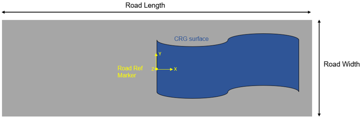
In order to represent complex terrain geometries, the soft soil road model enables the use of curved regular grid (CGR) files. For this, the attribute CRG_FILE=’path to .crg file’ needs to be set in the PARAMETERS block of the road (.rdf) file.
$---------------------------------------------------------------------PARAMETERS
[PARAMETERS]
 MU              =  1.0                 $ Friction coefficient
 LENGTH          =  300.0               $ Range of soil region in x direction
 WIDTH           =  6.0                 $ Range of soil region in y direction
 NODES           =  1                   $ Number of integration points
 MULTIPASS       =  'TRUE'
CRG_FILE = '<road_path>.crg'Deformable Road
MotionView provides the ability to include soft-soil road deformation in simulations using the soft-soil tire model. The deformable road graphic is created in MotionView using the Road Tools and sent to MotionSolve to simulate the tire-soft-soil dynamics. The soft-soil road deformation can be visualized in HyperView.
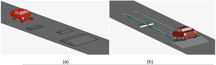
The Road Tool supports the creation of flat and Curved Regular Grid (.crg) roads using the road property file (.rdf). It is also possible to include the different obstacle types available in the soft-soil tire model that deforms along with the road depending on the obstacle material. Refer to Obstacles for more information.
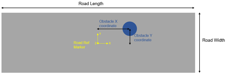
Road Positioning
Add a Soft-Soil Deformable Road and Visualize the Results
- Load the soft-soil road property file (.rdf) in the Road Tools
(see the Visualization - Road Tools topic for additional
information). When loading the road property file, an .h3d file and .mdl file are created at the selected path. The road graphics are displayed in MotionView's modeling windows and a graphic system containing the road graphics is defined in the model browser.
Figure 6. 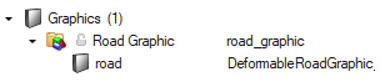
- Add the soft-soil tire and road property files in the Tires entity or use the track builder to create a track system with soft soil.
- Run the analysis in MotionSolve.
MotionSolve reads the road .h3d created by the Road Tools and generates an additional SSR (soft-soil road) file which has the name <MotionSolve_result_xml_name>_softsoil_road.ssr during run time. The softsoil_road.ssr contains the information about the road graphic nodes deformed during the simulation.
- Post-process the analysis in HyperView.
Once the simulation in completed, open the model animation results in HyperView.