Orientation
Use the Orientation tool to align an entity along a particular direction.
- Vector
- Joints
- Bushings
- Markers
- Gears
There are two types of orientation tools.
- VectorOrientation
- This tool orients on an axis or a vector. This tool is used to orient
the following entities:
- Vectors
- Non-compliant Joints
When in the edit context of an entity listed above, click on the Orientation tool. The VectorOrientation tool appears.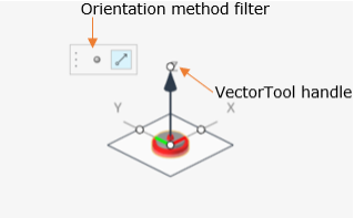
Figure 1. The tool is made up of a vector arrow indicating the direction and a plane orthogonal to the vector direction. The arrow tip has a circular handle. The tool is also accompanied with a microdialog containing a Point and a Vector icon to use as a filter for the method of orientation.
- MarkerOrientation
- This tool orients a reference frame by the Axis-Plane method and is used
to orient:
- Markers
- Bushings and Compliant Joints
When in the edit context of entity listed above, click on the Orientation tool. The MarkerOrientation tool appears.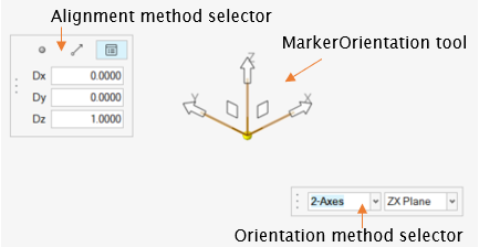
Figure 2. The tool is made up of three directional vectors and two microdialogs:- Axes-Plane selector to choose Axes and Plane.
- Filter for the method of orientation (containing a Point, Vector, and Direction Cosines icon).
- To orient:
- Select the 1-Axis or 2-Axes in the Orientation method
selector.
- 1-Axis orients the entity using only one axis. The remaining axes are oriented automatically.
- 2-Axes method orients the entity requires information for two axes.
- Click on one direction vector (X,
Y , or Z) to
select the primary axis of orientation.
- If 2-Axes is selected, the planes associated with the selected vector gets displayed in the tool as well as listed in the Axes-Plane selector.
- Use the Alignment method filter to align
the axis either along a point, a vector, or use the direction
cosine.
- Hold the handle at the vector end, rotate around.
- Hover over a Point (a Point entity of CAD vertex) or a Vector based on the orientation method chosen on the filter.
- Once the desired aligning entity is highlighted, release the mouse to select the highlighted entity. The axis will be aligned along the selected direction.
- If 2-Axes is selected, click on the Plane
handle. The handle is selected.
- Hover and click over a Point (a Point entity of CAD vertex) or a Vector (a Vector entity or CAD edge) based on the orientation method chosen on the filter.
- The second axis will be aligned such that, the selected reference lies in the plane formed by the two axes of the entity.

Figure 3. Depiction of the XZ plane of the marker containing Point 2 used for orientation
- Select the 1-Axis or 2-Axes in the Orientation method
selector.